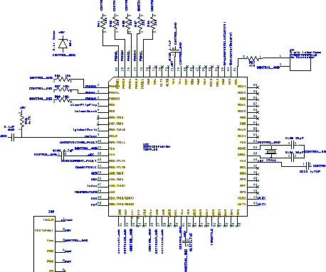
I've been looking at migrating to the DSPIC30F6010A. So far, I've migrated the connections from the 4010 to the 6010A:

So, some good news:
The problem of sharing the QEI inputs with the resolver inputs goes away. It's possible to re-configure the synchronized input selection to allow this, mainly because there are more analog input pins. You can use 4 synchronized inputs maximum.
For synchronized analog input there could be these set-up choices
a) 4 synchronized current sensors - AN6, AN7, AN8, AN9. These would be fixed in hardware.
b) 2 synchronized current sensors and two synchronized resolver inputs - AN5, AN4, AN6, AN7 - Note that AN4 and AN5 would be swapped from QEA and QEB
There are 14 available analog input pins, AN0 and AN1 must be used for the programmer.
Between the PWM pins and the analog input pins on the left side there are 6 pins that can be used for fault detection/correction.
There are two CAN buses available, at the top of the IC.
The RDXX pins at the top of the IC can be used for digital output, like blinky lights and relay control, etc.
On the right side of the IC, there's UART 1, and I^2C connection and/or a bunch of digital I/O.
On the bottom, there's analog I/O and 4 pins for digital input and/or another UART.
I'm trying to group stuff according to function. I think it may make routing the circuit board easier. I'd like to make it a 2 layer board if possible.
Suggestions?
- E*clipse