 10-30-2015, 07:03 PM
|
#2261 (permalink)
|
|
Permanent Apprentice
Join Date: Jul 2010
Location: norcal oosae
Posts: 523
Thanks: 351
Thanked 314 Times in 215 Posts
|
I've been looking at migrating to the DSPIC30F6010A. So far, I've migrated the connections from the 4010 to the 6010A:
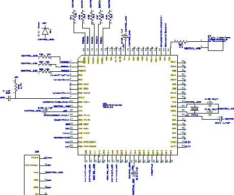
So, some good news:
The problem of sharing the QEI inputs with the resolver inputs goes away. It's possible to re-configure the synchronized input selection to allow this, mainly because there are more analog input pins. You can use 4 synchronized inputs maximum.
For synchronized analog input there could be these set-up choices
a) 4 synchronized current sensors - AN6, AN7, AN8, AN9. These would be fixed in hardware.
b) 2 synchronized current sensors and two synchronized resolver inputs - AN5, AN4, AN6, AN7 - Note that AN4 and AN5 would be swapped from QEA and QEB
There are 14 available analog input pins, AN0 and AN1 must be used for the programmer.
Between the PWM pins and the analog input pins on the left side there are 6 pins that can be used for fault detection/correction.
There are two CAN buses available, at the top of the IC.
The RDXX pins at the top of the IC can be used for digital output, like blinky lights and relay control, etc.
On the right side of the IC, there's UART 1, and I^2C connection and/or a bunch of digital I/O.
On the bottom, there's analog I/O and 4 pins for digital input and/or another UART.
I'm trying to group stuff according to function. I think it may make routing the circuit board easier. I'd like to make it a 2 layer board if possible.
Suggestions?
- E*clipse
|
|
|

|
|
The Following 3 Users Say Thank You to e*clipse For This Useful Post:
|
|
 Today Today
|
|
|
|
 Other popular topics in this forum...
|
|
|
|
|
10-30-2015, 07:23 PM
|
#2262 (permalink)
|
|
PaulH
Join Date: Feb 2008
Location: Maricopa, AZ (sort of. Actually outside of town)
Posts: 3,832
Thanks: 1,362
Thanked 1,202 Times in 765 Posts
|
Looks good! You can actually still use the PGD & PGC for the programmer AND for the analog inputs, and still not lose your debugging ability. You just tie PGD to EMUDx and PGC to EMUCx (for any x that is convenient). EMUD and EMUC are alternate debugging pins. So, you would include a toggle switch. You switch it to state A to program it, then switch it to state B to either debug the program, or just run the program like normal, using those pins as analog. I'm doing that this time with a project for my job.
|
|
|
|
|
The Following 3 Users Say Thank You to MPaulHolmes For This Useful Post:
|
|
|
10-30-2015, 08:01 PM
|
#2263 (permalink)
|
|
Permanent Apprentice
Join Date: Jul 2010
Location: norcal oosae
Posts: 523
Thanks: 351
Thanked 314 Times in 215 Posts
|
Quote:
Originally Posted by MPaulHolmes

Looks good! You can actually still use the PGD & PGC for the programmer AND for the analog inputs, and still not lose your debugging ability. You just tie PGD to EMUDx and PGC to EMUCx (for any x that is convenient). EMUD and EMUC are alternate debugging pins. So, you would include a toggle switch. You switch it to state A to program it, then switch it to state B to either debug the program, or just run the program like normal, using those pins as analog. I'm doing that this time with a project for my job.
|
Thank you very much! 
Originally I was thinking about using the EMUD1 and EMUC1 pins 59,60 in the upper right corner for this purpose. It just seemed easier for all the debugging/programming you're doing to not mess with switching back and forth. 
I'll leave pin 59 and 60 open for this purpose if two more analog inputs are absolutely necessary.
I'm also trying to leave pins open in various places so this design can evolve easily. For example, pins 6 and 7 have a CNx option, so if future fault interrupts or clearing capability is needed it can be added no problem.
Could you post a list of stuff you'd like to add? It would help make to sure I leave pins open for it.
- E*clipse |
|
|
|
|
The Following 2 Users Say Thank You to e*clipse For This Useful Post:
|
|
|
10-30-2015, 08:25 PM
|
#2264 (permalink)
|
|
Permanent Apprentice
Join Date: Jul 2010
Location: norcal oosae
Posts: 523
Thanks: 351
Thanked 314 Times in 215 Posts
|
On the subject of current sensing -
After more thought, I'd like to stay away from splitting the output busbars/pins/etc in order to add current sensing.
While the part P-hack suggested looks like a very good solution for this problem, it would still require adding a controlled impedance section... I suppose this could just be a thin part in one of the bus bars or connector pins... hmmm
The other option that would require this are the Allegro current sensors that are soldered to the bus bar.
In a general sense, I think non-contact sensors that use the magnetic field should be accurate enough for our purposes. Some of them require a flux concentrator, which is a gapped ferrite or laminate ring that goes around the sensed wire. The sensor fits in the gap. This would require some magnetic design to get right, but the ferrite might also serve the purpose of reducing stray EMI. A device from Allegro would be directly solderable to the main board with through hole pins, but would require an external field concentrator.
How do you guys feel about the issue of designing an external magnetic part (like a gapped torroid) for this?
Another option - would be the hall-effect sensors that don't require an external field concentrator. There is one made by Melexis that can do this and measure large nearby currents: - I think this is the one Paul made the daughter board for.
The MLX91206 is a contactless programmable current sensor
some advantages:
Isolated from high power circuit
Don't need external magnetics
Are spec'd for automotive use - - -50C to 150C storage and -40C to 150C operation.
Analog or PWM output
Issues:
requires calibration/programming
would require a separate "daughter board" that is perpendicular to the main circuit board.
- E*clipse |
|
|
|
|
The Following User Says Thank You to e*clipse For This Useful Post:
|
|
|
10-31-2015, 01:18 AM
|
#2265 (permalink)
|
|
Master EcoModder
Join Date: Sep 2010
Location: Saskatoon, canada
Posts: 1,488
Thanks: 746
Thanked 565 Times in 447 Posts
|
Quote:
Originally Posted by e*clipse
After more thought, I'd like to stay away from splitting the output busbars/pins/etc in order to add current sensing.
|
Not sure I have a good enough understanding to offer a specific comment. Splitting busbar is a bit tough for DIY with hand tools.. at least to do it accurately.
Quote:
|
While the part P-hack suggested looks like a very good solution for this problem, it would still require adding a controlled impedance section... I suppose this could just be a thin part in one of the bus bars or connector pins... hmmm
|
Shunts are available that can be embedded. Not sure on the cost. I'd avoid narrowing sections of the bus or connections. The shunt designers put a lot of effort into temperature compensation and laser trimming of the shunts to get 5% or 1% (or 0.1% if you want to pay that much) accuracy.
Quote:
|
The other option that would require this are the Allegro current sensors that are soldered to the bus bar.
|
Soldering to bus bar - do you do that with a torch? Copper dissipates the heat pretty well ...
Quote:
In a general sense, I think non-contact sensors that use the magnetic field should be accurate enough for our purposes. Some of them require a flux concentrator, which is a gapped ferrite or laminate ring that goes around the sensed wire. The sensor fits in the gap. This would require some magnetic design to get right, but the ferrite might also serve the purpose of reducing stray EMI. A device from Allegro would be directly solderable to the main board with through hole pins, but would require an external field concentrator.
How do you guys feel about the issue of designing an external magnetic part (like a gapped torroid) for this?
|
Magnetic design is so far out of my competence that I am at a loss for a good comparison ... I'd likely be better at rocket science? If I can avoid magnetic design, I will.
Quote:
Another option - would be the hall-effect sensors that don't require an external field concentrator. There is one made by Melexis that can do this and measure large nearby currents: - I think this is the one Paul made the daughter board for.
The MLX91206 is a contactless programmable current sensor
some advantages:
Isolated from high power circuit
Don't need external magnetics
Are spec'd for automotive use - - -50C to 150C storage and -40C to 150C operation.
Analog or PWM output
Issues:
requires calibration/programming
would require a separate "daughter board" that is perpendicular to the main circuit board.
|
I believe that I read about a hall effect sensor that uses AC excitation to cancel some of the drift and calibration requirements. EVTV sells a version, but it is CANbus only if I recall. Someone else should sell a competitive product by now - EVTV Motor Verks Store: LEM CAB300-C Flux Gate Current Sensor, Meters and Instruments, CAB300 |
|
|
|
|
The Following User Says Thank You to thingstodo For This Useful Post:
|
|
|
10-31-2015, 10:17 AM
|
#2266 (permalink)
|
|
PaulH
Join Date: Feb 2008
Location: Maricopa, AZ (sort of. Actually outside of town)
Posts: 3,832
Thanks: 1,362
Thanked 1,202 Times in 765 Posts
|
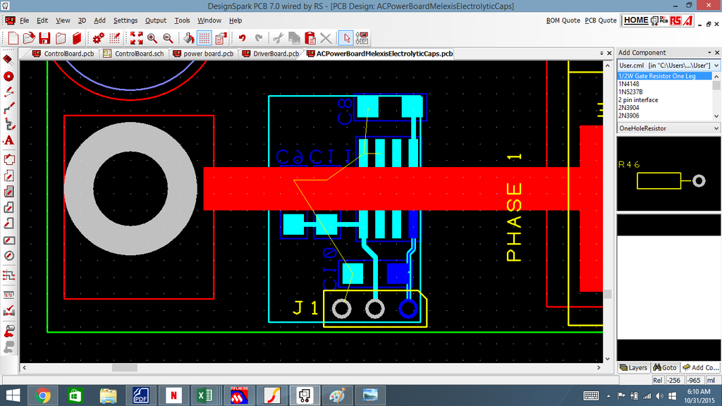
Melexis has several variations on the SOIC8 part now. Some of them are programmable, but they also still have the original ones that aren't programmable. You can follow the formulas in their application note to get you within maybe 10%, and then try it out and calibrate it once. Then, as long as the mechanical things are the same, different sensors will give the same results. I'm using the melexis on that 50kW AC power board with no daughter board. There's bare copper to solder a little rectangle piece of wire on that narrow path to allow the higher current:
 |
|
|
|
|
The Following User Says Thank You to MPaulHolmes For This Useful Post:
|
|
|
10-31-2015, 02:54 PM
|
#2267 (permalink)
|
|
Permanent Apprentice
Join Date: Jul 2010
Location: norcal oosae
Posts: 523
Thanks: 351
Thanked 314 Times in 215 Posts
|
Quote:
Originally Posted by MPaulHolmes
Melexis has several variations on the SOIC8 part now. Some of them are programmable, but they also still have the original ones that aren't programmable. You can follow the formulas in their application note to get you within maybe 10%, and then try it out and calibrate it once. Then, as long as the mechanical things are the same, different sensors will give the same results. I'm using the melexis on that 50kW AC power board with no daughter board. There's bare copper to solder a little rectangle piece of wire on that narrow path to allow the higher current:
|
It's good to know you're familiar w/ the Melexis product and happy with it.
I did notice that some of the Melixis sensors were set up for use like you illustrate above, with internal flux concentrators, and others are set up for external flux concentrators.
It seems that the ones with internal flux concentrators might need an external shield:
Melexis: Hall-effect Position Sensors | Sensorless BLDC Motor Drivers
The other version uses a concentrator, which is sort of like a toroid with a gap. The sensor fits inside the gap, as illustrated in the reference. The problem is you can't use a ferrite torroid, as they saturate too easily, according to an Allegro app note on magnetic design:
Allegro MicroSystems - Guidelines for Designing a Concentrator for High-Current Sensing Applications with an Allegro Hall-Effect Sensor IC
After reading the app notes, I felt I could spec the necessary magnetic elements. Problem is finding the dang things.  So far I've had no luck finding a toroidal ring made of steel laminates, either tape wound or stacked. There are lots of ferrite toroids out there - maybe there's one that won't saturate, I have no idea.
I think it would be relatively easy to design/make a shield, like the ones shown in the Melexis app note. If it wasn't made of the right steel, etc etc it would probably work fine anyway. This seems like a good DIY part.
So, being indecisive, I've decided to do this for the control board. Every current sensor I've considered has these electrical connections: gnd, +5V, output. The Tamura sensors use a lot of board real-estate but are the easiest solution. Unfortunately they won't work so well for folks in cold climates. So I'm going to leave enough board space for the sensors and put in through hole connectors for Melexis and Allegro sensors as well. It will require no extra board space and very little extra wiring and no extra cost. In programming, all sensors will need to be calibrated anyway. Folks can mess around with whatever they want. 
Personally, I'm going with the solution Paul Illustrated above. Melexis makes automotive qualified parts that can take an extended temperature range. In the round inverter design, it will require a daughter board because I'm going to sense the current in the output connector pins that can range up to 300A.
- E*clipse
|
|
|
|
|
The Following User Says Thank You to e*clipse For This Useful Post:
|
|
|
10-31-2015, 03:07 PM
|
#2268 (permalink)
|
|
PaulH
Join Date: Feb 2008
Location: Maricopa, AZ (sort of. Actually outside of town)
Posts: 3,832
Thanks: 1,362
Thanked 1,202 Times in 765 Posts
|
It works good without a shield as long as there is some distance away from the unwanted currents. They fall off REALLY fast. Something 1 inch away has almost no effect when compared to 0.0625" away. And currents that are perpendicular to the current you are measuring don't have an effect either. I remember, with a 0.125" thick daughter PCB right on the bus bar, the current sensor range was about -1200amp to 1200amp. A 0.0625" PCB gave a range of maybe -300amp to 300amp or something like that. At 0.5" away, you could probably measure -10,000amp to 10,000amp. So, if there is a spurious current 1 inch away, even if it's a few hundred amps, it's not going to have much effect.
|
|
|
|
|
The Following User Says Thank You to MPaulHolmes For This Useful Post:
|
|
|
11-01-2015, 12:57 AM
|
#2269 (permalink)
|
|
Permanent Apprentice
Join Date: Jul 2010
Location: norcal oosae
Posts: 523
Thanks: 351
Thanked 314 Times in 215 Posts
|
Quote:
Originally Posted by MPaulHolmes
It works good without a shield as long as there is some distance away from the unwanted currents. They fall off REALLY fast. Something 1 inch away has almost no effect when compared to 0.0625" away. And currents that are perpendicular to the current you are measuring don't have an effect either. I remember, with a 0.125" thick daughter PCB right on the bus bar, the current sensor range was about -1200amp to 1200amp. A 0.0625" PCB gave a range of maybe -300amp to 300amp or something like that. At 0.5" away, you could probably measure -10,000amp to 10,000amp. So, if there is a spurious current 1 inch away, even if it's a few hundred amps, it's not going to have much effect.
|
That sound very easy - very DIY.
So, calibrated daughter board thicknesses directly tied to the output pin would give reasonable results. Real accuracy could be dialed in by programming the Melexis IC's and the AtoD results. That sounds great.
If I run into any issues with interference, I could provide a general purpose shield design, which could use normal, easy to obtain steel and be easy to make with tin snips and a hand drill.
Excellent! Maybe this is the "easy" solution and just using the Melexis IC would work for all cases. This would save both design trouble and board real-estate.
- E*clipse |
|
|
|
|
11-01-2015, 03:01 AM
|
#2270 (permalink)
|
|
EcoModding Lurker
Join Date: Nov 2015
Location: India
Posts: 3
Thanks: 0
Thanked 0 Times in 0 Posts
|
Paul, First up you're a god. I've been looking over this thread now and then for maybe an year now and you have finally made me register on the forum and get back into trying to do vector control.
Was desperate to successfully do vector control about a year back and gave up back then but want to get back into it and just do it this time around.
When I gave up, I knew practically nothing. But after that I made a PI based current controller for a simple RL load using a dsPIC33 and an H-Bridge and that has given me confidence.
I'm going to read the entire 227 pages of this thread but while that happens, please tell me a bit about how you tackled the whole rotor time constant and PI tuning problems.
Have you thought of sensorless or will the performance not be good enough as with a sensor?
Did you just modify the dsPIC code or write it from scratch yourself? I am generally wary of using other people's codes out of fear that I won't be able to debug and properly modify it.
|
|
|
|
|


