Quote:
Originally Posted by MPaulHolmes

Melexis has several variations on the SOIC8 part now. Some of them are programmable, but they also still have the original ones that aren't programmable. You can follow the formulas in their application note to get you within maybe 10%, and then try it out and calibrate it once. Then, as long as the mechanical things are the same, different sensors will give the same results. I'm using the melexis on that 50kW AC power board with no daughter board. There's bare copper to solder a little rectangle piece of wire on that narrow path to allow the higher current:
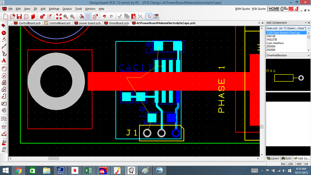 |
It's good to know you're familiar w/ the Melexis product and happy with it.

I did notice that some of the Melixis sensors were set up for use like you illustrate above, with internal flux concentrators, and others are set up for external flux concentrators.
It seems that the ones with internal flux concentrators might need an external shield:
Melexis: Hall-effect Position Sensors | Sensorless BLDC Motor Drivers
The other version uses a concentrator, which is sort of like a toroid with a gap. The sensor fits inside the gap, as illustrated in the reference. The problem is you can't use a ferrite torroid, as they saturate too easily, according to an Allegro app note on magnetic design:
Allegro MicroSystems - Guidelines for Designing a Concentrator for High-Current Sensing Applications with an Allegro Hall-Effect Sensor IC
After reading the app notes, I felt I could spec the necessary magnetic elements. Problem is
finding the dang things.

So far I've had no luck finding a toroidal ring made of steel laminates, either tape wound or stacked. There are lots of ferrite toroids out there - maybe there's one that won't saturate, I have no idea.
I think it would be relatively easy to design/make a shield, like the ones shown in the Melexis app note. If it wasn't made of the right steel, etc etc it would probably work fine anyway. This seems like a good DIY part.
So, being indecisive, I've decided to do this for the control board. Every current sensor I've considered has these electrical connections: gnd, +5V, output. The Tamura sensors use a lot of board real-estate but are the easiest solution. Unfortunately they won't work so well for folks in cold climates. So I'm going to leave enough board space for the sensors and put in through hole connectors for Melexis and Allegro sensors as well. It will require no extra board space and very little extra wiring and no extra cost. In programming, all sensors will need to be calibrated anyway. Folks can mess around with whatever they want.

Personally, I'm going with the solution Paul Illustrated above. Melexis makes automotive qualified parts that can take an extended temperature range. In the round inverter design, it will require a daughter board because I'm going to sense the current in the output connector pins that can range up to 300A.
- E*clipse