I did some testing of various vortex generators on the A-pillar of the Insight. I've previously seen some flow separation immediately behind the pillar on the side glass.
Initially I decided to see if I could measure a pressure change on the side glass.
Test:
- Honda Insight
- Magnehelic 0-3 inch of water gauge, converted to Pa
- Reference pressure pitot tube static port 2.2m above ground
- 80 km/h
- Two way average
- Light winds, 15 degrees C
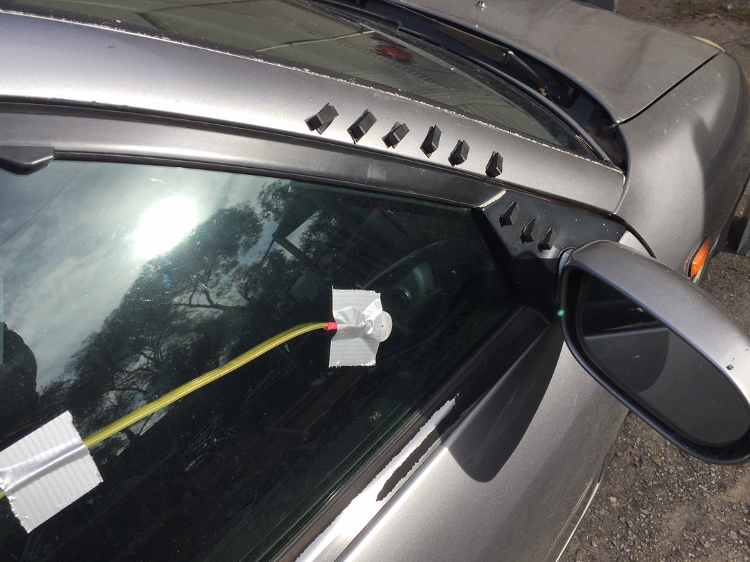
- Sensor puck on side glass as pictured
No VGs: -149 Pa
5 Stolspeed VGs aligned horizontally: -167 Pa
5 Stolspeed VGs angled up from horizontal: -162 Pa
I then fitted rubber wedge VGs.
5 wedges aligned horizontally: -167 Pa
9 wedges aligned horizontally (as shown in pic): -154 Pa
So basically none of these did very much.
I then decided that I was trialling stuff that was too small, and to go for a monster. I then fitted one Airtab.

1 Airtab: -184 Pa
So that made a difference, presumably providing faster flow.
But what would tufts show?
No Airtab:

Airtab:

(The pressure sensing puck was located about where the middle tuft is.) So I wouldn't call that a success.
As I have previously posted, by far best results have come from using an aerofoil guide vane on the A pillar. (But I can't get an extrusion long enough and I don't want to make my own.)
Footnote: I was surprised at how low the measured pressure was at this location. It might be interesting to measure right down the side of the car, and see if the low pressure at this location is as a result of the A pillar. (Has anyone seen pressure measurements down the side of a car? I haven't.)