 06-02-2020, 06:57 PM
|
#21 (permalink)
|
|
EcoModding Lurker
Join Date: Mar 2009
Location: San Jose
Posts: 15
Thanks: 1
Thanked 7 Times in 7 Posts
|
I'll get a yard stick to get the measure points right. Suppose there are a million priuses out there that would love to know.
|
|
|

|
 Today Today
|
|
|
|
 Other popular topics in this forum...
|
|
|
|
 06-02-2020, 07:15 PM
|
#22 (permalink)
|
|
Cyborg ECU
Join Date: Mar 2011
Location: Coastal Southern California
Posts: 6,302
Thanks: 2,374
Thanked 2,176 Times in 1,471 Posts
|
Quote:
Originally Posted by gregersonke

I'll get a yard stick to get the measure points right. Suppose there are a million priuses out there that would love to know.
|
Exactly. Look forward to seeing what you post. You might even consider a dedicated thread for a write-up, since that would get you more attention.
__________________
See my car's mod & maintenance thread and my electric bicycle's thread for ongoing projects. I will rebuild Black and Green over decades as parts die, until it becomes a different car of roughly the same shape and color. My minimum fuel economy goal is 55 mpg while averaging posted speed limits. I generally top 60 mpg. See also my Honda manual transmission specs thread.


|
|
|

|
 06-02-2020, 07:38 PM
|
#23 (permalink)
|
|
Banned
Join Date: Nov 2017
Location: Australia
Posts: 2,060
Thanks: 107
Thanked 1,608 Times in 1,137 Posts
|
Quote:
Originally Posted by 4drviper

So, from #1 I understand that VGs will "attract" the center of pressure toward their downstream area.
And from #2 I understand that what I was going to do could easily (when overdone) worsen the crosswind instability by keeping the center of pressure even more off.
|
No, I don't think so, but I've never really thought about it in those terms. VGs just energise the boundary layer and so potentially give better flow attachment where separation is occurring.
Quote:
Originally Posted by 4drviper

I was also considering directly placing them on the A-pillar which would also deal with the buffeting with open window at medium to high speeds. So I start at the bottom of A-pillar and where should I stop?
|
No idea. Testing is king.
Quote:
Originally Posted by 4drviper

For some reason I feel putting them on the roof between the top of B and C-pillars would be effective.
|
No I don't think so.
Quote:
Originally Posted by 4drviper

Speaking of 1G Insight, are you the person who wrote Autospeed blog? That's where I read about the idea to place airtabs under the car.
|
Yes I was employed as editor at AutoSpeed for a long time. The very brief mention I made there of putting AirTabs under the car was very anecdotal - and was stated as such. There's far more detail, testing and analysis of VGs in my book. |
|
|

|
|
The Following User Says Thank You to JulianEdgar For This Useful Post:
|
|
 06-09-2020, 03:40 AM
|
#24 (permalink)
|
|
Banned
Join Date: Nov 2017
Location: Australia
Posts: 2,060
Thanks: 107
Thanked 1,608 Times in 1,137 Posts
|
Quote:
Originally Posted by JulianEdgar

I now have 40 of the Stolspeed VGs on their way. Very cheap including postage to the other side of the world - AUD$40. Good guy to communicate with too.
 |
The Stolspeed VGs arrived. I didn't realise that they were coming from within Australia - no wonder postage was cheap!

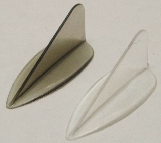
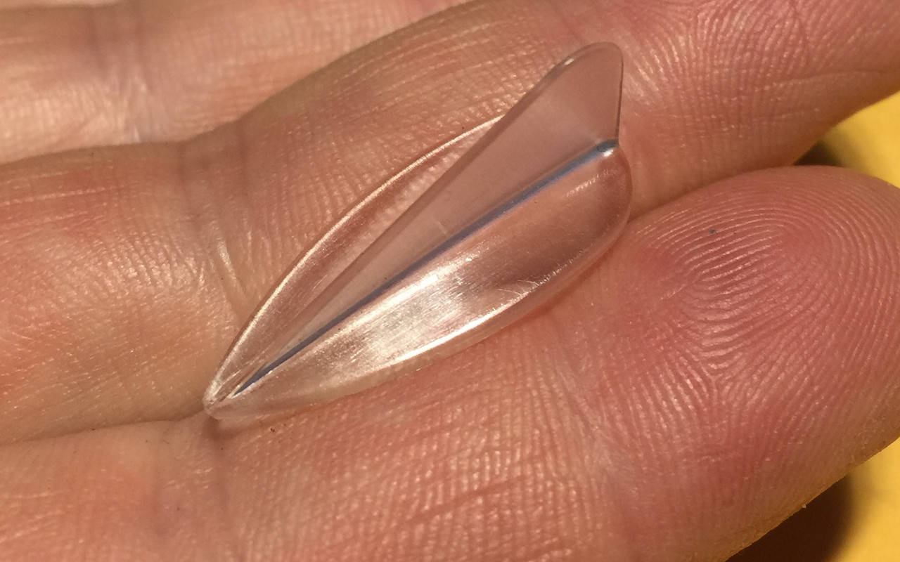
They are indeed very small - 24.7mm long, 10.3mm wide and 10.9mm high. With their claims of being flexible, I thought they'd be a bit rubbery but the plastic is still quite hard. It 'gives', but only a little. I think they'd cut someone if they fell on them and the VGs contacted bare skin. The upright is only 0.7mm thick.
They come with a sheet of double-sided adhesive that has been template-cut to suit the shape of their base.
In car use my guess is that they'd be suitable only for A pillars, and between the A mirror and pillar. They might also be suitable for the bonnet/hood, as the OP nominated. I might do some testing tomorrow.
|
|
|

|
|
The Following User Says Thank You to JulianEdgar For This Useful Post:
|
|
 06-09-2020, 12:27 PM
|
#25 (permalink)
|
|
EcoModding Lurker
Join Date: Oct 2017
Location: USA
Posts: 32
Accord - '12 Honda Accord sedan EX-L 90 day: 25.99 mpg (US)
Thanks: 9
Thanked 9 Times in 9 Posts
|
I have so far started to reconsider the arrangement on the hood after some 8 hours of tuft testing. A-pillar sounds more viable. And I feel I'm not qualified enough to touch the interactio between A-pillar vortex and the side mirror wake so I'm interested to see some testings from someone with vastly more knowledge than myself.
__________________

|
|
|

|
 06-09-2020, 04:24 PM
|
#26 (permalink)
|
|
Master EcoModder
Join Date: Aug 2012
Location: northwest of normal
Posts: 29,301
Thanks: 8,334
Thanked 9,092 Times in 7,509 Posts
|
If the goal is to raise pressure on the leeward side in a crosswind, Maybe you can achieve your goal with a roof-top strake.
 https://www.mrn.com/wp-content/uploa...-Las-Vegas.jpg
These are designed to kill lift when driving sideways, but they should have the same effect as a Gurney flap/wickerbill at the rear rolling vortexes down the lee side.
__________________
.
.Without freedom of speech we wouldn't know who all the idiots are. -- anonymous poster
___________________
.
.Impossible is just something we haven't done yet. -- Langley Outdoors Academy
|
|
|

|
|
The Following User Says Thank You to freebeard For This Useful Post:
|
|
 06-09-2020, 05:41 PM
|
#27 (permalink)
|
|
Banned
Join Date: Nov 2017
Location: Australia
Posts: 2,060
Thanks: 107
Thanked 1,608 Times in 1,137 Posts
|
Quote:
Originally Posted by 4drviper

I have so far started to reconsider the arrangement on the hood after some 8 hours of tuft testing.
|
Well, don't leave us in suspense - what were the results?! |
|
|

|
 06-10-2020, 02:26 AM
|
#28 (permalink)
|
|
Banned
Join Date: Nov 2017
Location: Australia
Posts: 2,060
Thanks: 107
Thanked 1,608 Times in 1,137 Posts
|
I did some testing of various vortex generators on the A-pillar of the Insight. I've previously seen some flow separation immediately behind the pillar on the side glass.
Initially I decided to see if I could measure a pressure change on the side glass.
Test:
- Honda Insight
- Magnehelic 0-3 inch of water gauge, converted to Pa
- Reference pressure pitot tube static port 2.2m above ground
- 80 km/h
- Two way average
- Light winds, 15 degrees C
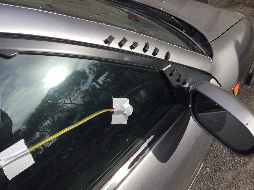
- Sensor puck on side glass as pictured
No VGs: -149 Pa
5 Stolspeed VGs aligned horizontally: -167 Pa
5 Stolspeed VGs angled up from horizontal: -162 Pa
I then fitted rubber wedge VGs.
5 wedges aligned horizontally: -167 Pa
9 wedges aligned horizontally (as shown in pic): -154 Pa

So basically none of these did very much.
I then decided that I was trialling stuff that was too small, and to go for a monster. I then fitted one Airtab.

1 Airtab: -184 Pa
So that made a difference, presumably providing faster flow.
But what would tufts show?
No Airtab:

Airtab:

(The pressure sensing puck was located about where the middle tuft is.) So I wouldn't call that a success.
As I have previously posted, by far best results have come from using an aerofoil guide vane on the A pillar. (But I can't get an extrusion long enough and I don't want to make my own.)
Footnote: I was surprised at how low the measured pressure was at this location. It might be interesting to measure right down the side of the car, and see if the low pressure at this location is as a result of the A pillar. (Has anyone seen pressure measurements down the side of a car? I haven't.) |
|
|

|
 06-10-2020, 03:49 PM
|
#29 (permalink)
|
|
Master EcoModder
Join Date: Jan 2008
Location: Sanger,Texas,U.S.A.
Posts: 16,477
Thanks: 24,502
Thanked 7,436 Times in 4,817 Posts
|
think
Quote:
Originally Posted by 4drviper

Taken the idea from modern airliners' nacelle strakes which is basically a huge VG on the side of the engine parallel to the airflow in level flight. Let's say the angle between the airflow and lengthwise centerline of VG, θ is 0 here. At level flight, the θ is 0 so no vortex is generated and marginal amount of drag introduced.
Now imagine the aircraft still moving level, but pitched up ~20 degrees; the airflow remains the same but the plane is turned up, resulting in θ = 20.
NOTE : In case you didn't know, it took me years until I was able to finally grasp the reality that airplanes rarely fly in line with the centerline of fuselage outside cruise. They pitch up and still slide forward (and downward a bit when landing) to create more lift at less airspeed but less efficiently. Which is why the VG is "under" the bottom of the wing but the air through the VG flows over the wing.
Now how is this relevant to a car? I can't actively pitch my car up or roll it to help turning, but the wind changes and I have to yaw (steer) the car to counteract the sideways forces which is never constant. And VGs on the trailing edge of a body seem to help "pressure recovery" as seen in the airtab wind tunnel civic data.
I've played around with several dozens of airtabs for past 5 years and even had 6 airtabs along the top of the rear window nearly eliminating any gusts when the weather app said up to 30mph.
Here's a little side note. For every airtab placed anywhere on the top or the side of 2007 Acura TL, it decreased my highway MPG pretty linearly by approximately ~0.5%. I tested from 2 to 12 airtabs using OBD2 fuel consumption data on a roundtrip of 7 miles (2 rural exits on the interstate little over 3 miles away) averaging around 21MPG.
Anyway, I concluded that airtabs having 1" height is the thickness of laminar flow at the end of 80ft box, not on a 15ft car. I needed something with less height as these are going to be placed across the hood, along the transverse frontal edges of stagnation bubble in the transition from hood to windshield. Airtabs could work in a pinch, but they're not as efficient (ECOmodder right?) being too tall for the airflow.
So what fits my bill? DIY VGs for general aviation planes.
These are 3/8" high and rigid.
https://www.blackmaxbrakes.com/airwa...tex-generators
These look about the same but flexible.
https://www.stolspeed.com/
Both are less than $1 / piece, less than $1.375(2.75/2) / piece for Airtab.
Since I don't want people tripping and falling on my car's hood and suing me for the "dangerous barbed plastic pieces" on my car, I decided to go with the soft one.
Some advantages
- Designed to work around 60mph (40-60kts in testimonies)
- Clear color (most won't bother to notice)
- Semi-flexible (no injury)
- Removable, semi-permanent, paint safe adhesive unlike airtabs' the "Ultimate Epoxy in Sponge form" which never comes off clean.
- (PROBABLY) not going to induce much drag even if I fail to install it at exactly θ = 0 since they're meant to be on an airplane without inducing too much drag at an angle at all times.
After finding out the direction of airflow with tuft test, they will be placed in a obtuse V-shaped arrangement with the pointy side forward, aligned θ = 0 in no crosswind airflow.
MS Paint drawing to help visualize...

Some visualization of airflow around a sedan in crosswind. From this link
https://hal.archives-ouvertes.fr/hal-01449542/document on page 8 by Rossitto et. al.

Whatcha think?? |
I've no knowledge of anyone actually optimizing VG type, number, and location placement outside a laboratory environment.
Also, I believe that if you read the report on the Mitsubishi Lancer Evo VG research, that the TBL was an inch thick at the rear of the EVOs roof.
If you're not running a university supercomputer and Dassault-Exa POWERFLOW CFD software, you can expect nothing from any lesser CFD.
The cheapest wind tunnel you could get into is A2, in Mooresville, North Carolina. Two hour minimum,at a beginning $480/ hour, then $ 500/hour afterwards. And you'll catch hell from a certain member for not spending $4,000/ hour at Gene Haas Racing' moving-floor wind tunnel.
I strongly recommend you look at the other end of the car for mods.
__________________
Photobucket album: http://s1271.photobucket.com/albums/jj622/aerohead2/
|
|
|

|
 06-11-2020, 12:15 AM
|
#30 (permalink)
|
|
Banned
Join Date: Nov 2017
Location: Australia
Posts: 2,060
Thanks: 107
Thanked 1,608 Times in 1,137 Posts
|
Quote:
Originally Posted by JulianEdgar

Footnote: I was surprised at how low the measured pressure was at this location. It might be interesting to measure right down the side of the car, and see if the low pressure at this location is as a result of the A pillar. (Has anyone seen pressure measurements down the side of a car? I haven't.)
|
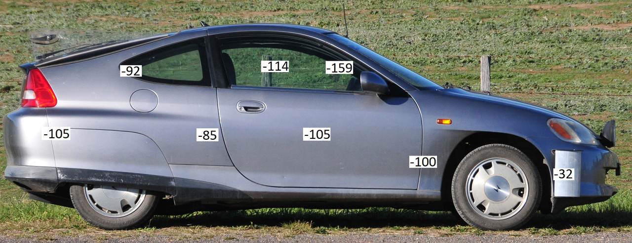
Pressures on side of Insight.
- 80 km/h test speed
- Two way average
- AR1890 digital manometer, inches of water converted to Pascals
- Pitot tube static pressure ref, 2.2 metre from ground
- Custom measuring puck
- Light winds, 14 degrees C
- Front and rear undertrays, rear with diffuser. Edgarwit front air curtains.

Starting from front, the higher pressure recorded inside the Edgarwit means, I think, that the puck was disrupting flow (narrow gap here).
Generally -100 Pa down side of car at approx half-door height. Surprisingly good flow attachment after front wheel - no change in pressure here. (Would be interesting to test with and without Edgarwit.)
Pressure after edge of door - leakage through door seal? I would have thought I'd be able to hear this, so I don't know.
Upper side readings show really low pressure after A-pillar. I am guessing this is the base of a vortex - tufts here show some odd patterns (eg tufts on glass pointing upwards along pillar). Note that reading was on side glass, not on curve of pillar.
|
|
|

|
|