Those of you familiar with the Honda Civic VX know that it is a special 5th Generation Honda Civic (link:
Honda Civic (fifth generation) - Wikipedia, the free encyclopedia) model with a special engine which is optimized for fuel efficiency. The 49-state (aka Federal) version of this Honda Civic model came from the factory with a 5-wire wide band O2 sensor (aka Lean Air Fuel (LAF) sensor) and an ECU that could put the engine into lean burn mode, earning it an EPA rating (link:
Fuel Economy) of 39 city, 50 highway, 43 combined; one of the best EPA ratings I've ever seen for a gasoline-powered car after the Geo Metro XFi and the Honda Insight... Even the Toyota Prius hybrid does not have highway EPA ratings as high as the Federal Honda Civic VX

(Of course, I know that individual drivers can get significantly better than EPA ratings)
Unfortunately, due to the slightly higher NOx emmissions that lean burn produces and due to the higher emmissions standards that California has in place, the lean burn feature could not be made available in the new Honda Civic VX models sold within California. Instead, the California models have everything the Fed models do *except* that they have ECUs which do not allow lean burn and most have a standard 4-wire O2 sensor (though I cannot confirm it, I have read that some (or maybe all) '92 Cali models did come from the factory with the 5-wire wide band LAF sensor preinstalled). The EPA rating for the California model VX is still quite good at 37 city, 45 highway, 40 combined, but for those that are dedicated (addicted?) ecomodders, switching to the Federal ECU is a fairly simple and relatively inexpensive way to gain around 5 to 10% (if not more) in fuel economy.
The instructions on how to do this are available in a variety of forms at a variety of locations on the web, but when I searched, I did not find any comprehensive and cohesive instructions in one location... So I assembled the things I did find into this one How To. I guess what I'm trying to say is that none of what I've written here is "original". I will try to give credit where it is due, and I am only adding some clarification and some personal experience in the hopes it will help others.
My philosophy when doing the conversion on my car was to do a completely reversible conversion, in case I needed to convert back to the Cali version (with narrow band O2 sensor and Cali ECU) for either smogging or for selling the car, or in case I foinked up the work. Folks that don't have this concern may find it easier and faster to chop up the stock wiring to get things connected the way they want. These instructions are not for those folks.
Cali VX owners benefit from the fact that aside from the wiring under the hood to connect the wide band LAF sensor, all the other necessary wiring is already in the main wiring harness from the engine compartment to the OBD1 connector for the ECU. So there's no need to route wires through the firewall and hack them into the OBD1 connector. That makes even the "clean" conversion I describe here really easy.
If you happen to have one of the '92 Cali models that already includes the 5-wire wide band LAF sensors, then you are lucky dogs indeed... all you have to do is swap the ECU and you are done!!
Things you will need to go get:
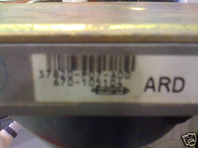
- Federal VX ECU: You should be able to find one of these used for relatively cheap on E-Bay. I found mine for $35, though I've seen it as high as $149. The thing to look for is the model number on the ECU... There should be a series of numbers, a dash, and then either P07-A00 or P07-A01. It does not matter which of those you get. The Cali models have P07-L00 or P07-L01.
Crappy pic of the Fed ECU label:
- Wide Band LAF sensor, model L1H1: You can get a brand new one from the Honda dealer, but that will probably run you ~$400. You may be able to find used ones on E-bay, though I'm not sure I would trust a well used one. Occasionally new ones pop up at Ebay for as little as $65, though the going price seems to be closer to $170 or so. I found a nearly new Honda Factory one on E-Bay for $175.
- A set of connectors: I found these at my local Pick-N-Pull (for those that don't know - this is where a person pays a small fee to wander into the wrecking yard to pull whatever parts are needed off the limited collection of wrecked autos there... and then pays a set fee for the item pulled); I got all the connectors I wanted for free (outside of the initial entrance fee, of course). You should be able to find the needed connectors under the hood of most Hondas; you do not necessarily need to find a VX or even a 5th generation Civic. I looked for (and found) connectors that matched in color to mine in Hondas that were roughly the same generation as mine, though I think it ended up being from an Accord's engine bay. You will need:
- One 4-pin male (needs pins 2 and 4)
- One 8-pin female
- One 6-pin male (needs all 6 pins)
- One 6-pin female
NOTE: I pointed out which pins are needed because there are some connectors in some cars that do not have all the pins needed for this project in them. I did not realize this until too late; I ended up with a 6-pin male that was missing one pin. Fortunately, I was able to scavenge a pin from the 4-pin connector, but it was a bugger getting it out so I could put it into the 6-pin male. If you can find connectors with the right pins in the right places to begin with, it'll save you some time.
NOTE: The pins are numbered a certain way in the Honda Service Manual; see the pics below. That is the numbering scheme I am referencing within these instructions.
This image is provided by user monroe74 on GasSavers.org - Fuel Efficiency, Save Gas and Gas Mileage Forum

In this image I show how the pins are numbered using the 6-pin male & female:

Places to harvest connectors from Hondas in the wrecking yard. The passenger shock tower will give you the 6-pin connectors; near the distributor sometimes gives you 4-pin and 8-pin connectors; and sometimes the area by the driver side shock tower has some 8-pin connectors too. Obviously, my VX has nothing on the driver side shock tower but some of the fancier models in the wrecking yard do.

Here is my collection of harvested connectors:

Once you have all the connectors, it's time to build the harness.
Tools you will need to make the harness:
- Soldering materials (iron, solder, etc)
- Wire strippers
- Electrical tape
- DMM (digital multi meter) or something with which you can test continuity
- Wiring diagram (see below)
- Wiring instructions (see below)
- Extra wire
TomO provided a nice image of the wiring diagram which showed the 4-wire O2 sensor and the 5-wire O2 sensor side-by-side:

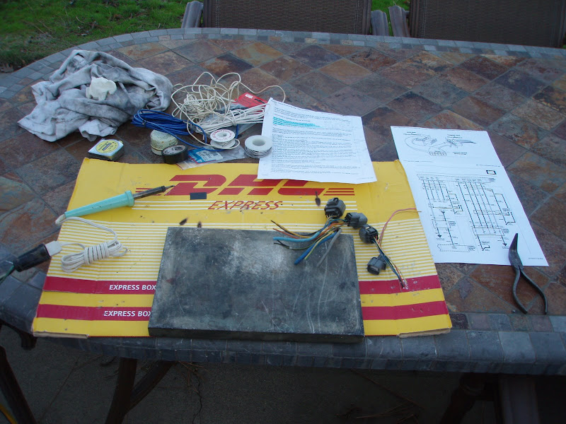
Here is my "work area" as I prepared to build the harness:
The best instructions I found for wiring the connectors together were written by user monroe74 in this thread:
Civic VX Lean Burn Questions - GasSavers.org. I've included the instructions here as well.
NOTE: The 8-pin and 4-pin connectors will be close to each other (near the LAF sensor), and the 6-pin male and female connectors will be close to each other (near the passenger shock tower connectors). The 8-pin male will have 4 wires that go to the 6-pin male; those 4 wires need to be about 2 feet long. There is another wire that goes from the 8-pin male to a ground point which needs to be about 1 1/2 ft long (18 inches). I found it helpful to know this ahead of time so that I could lay out the wires before I started the soldering.
Quote:
|
Originally Posted by monroe74
My goal is connect the new parts (ECU and O2 sensor) without cutting any existing wiring. I want to do it all via standard Honda connectors, so the installation will be easily reversible, without a trace.
Three ECU terminals (D3, D8 and D16) are used in the 49-state VX, but not in the CA VX. The good news is that the CA VX already has the needed wires in place in the main harness (at least this is true in my '95 CA VX; I verified this with a continuity test). This means if I create a custom harness, using 4 connectors, I can install the new O2 sensor without cutting any wires.
I was able to find the needed connectors at a junkyard. I didn't need to find a VX; the needed connectors are used in a bunch of different places on the other '92-'95 Civics. The needed connectors are as follows:
8-pin female
6-pin male
6-pin female
4-pin male
You create your custom harness by wiring them together as follows:
8-pin female.
pin 1 needs to be wired to 4-pin male, pin 4.
pin 2 needs to be wired to ground, G101.
pin 3 needs to be wired to 4-pin male, pin 2.
pin 4 needs to be wired to 6-pin male, pin 3.
pin 5 is not used.
pin 6 needs to be wired to 6-pin male, pin 2.
pin 7 needs to be wired to 6-pin male, pin 6.
pin 8 needs to be wired to 6-pin male, pin 5.
The wires from 4, 6, 7, and 8 need to be shielded, and the shield should be grounded.
6-pin male.
pins 2, 3, 5 and 6 are referenced above.
pin 1 needs to be wired to 6-pin female, pin 1.
pin 4 needs to be wired to 6-pin female, pin 4.
6-pin female.
pins 1 and 4 are referenced above. pins 2, 3, 5 and 6 are not used.
4-pin male.
pins 2 and 4 are referenced above. pins 1 and 3 are not used.
That's a total of eight connections that have to be made, to join these 4 connectors together to form your custom harness. (There's one more connection, a ground, that will be made when you're installing the harness on the car.)
The harness is installed on the car as follows:
8-pin female. Connects to new O2 sensor, C111.
6-pin male. Connects on shock tower, to female of C129.
6-pin female. Connects to male of old C129.
4-pin male. Connects to old C111 4-pin female (the connector your old O2 sensor was plugged into).
The following is reference information. It's stuff you don't really need to know. It's the wiring instructions, with extra information that could be useful if you want to know more about what's really going on. Or if you need to trace things for troubleshooting purposes.
8-pin female.
pin 1 needs to be wired to 4-pin male, pin 4. This line goes via C103, pin 2, and ultimately reaches A6.
pin 2 needs to be wired to ground, G101.
pin 3 needs to be wired to 4-pin male, pin 2. This line goes via C103, pin 9, and ultimately reaches D22. A6 and D22 were in use in connection with the old O2 sensor, so we're taking advantage of the existing plug and wiring.
pin 4 needs to be wired to 6-pin male, pin 3. This line goes via C129, pin 3, and ultimately reaches D3. The old O2 sensor did not use D3. But we're taking advantage of the fact that C129 already is connected to D3, even in a CA VX.
pin 5 is not used.
pin 6 needs to be wired to 6-pin male, pin 2. This line goes via C129, pin 2, and ultimately reaches D8. The old O2 sensor did not use D8. But we're taking advantage of the fact that C129 already is connected to D8, even in a CA VX.
pin 7 needs to be wired to 6-pin male, pin 6. This line goes via C129, pin 6, and ultimately reaches D14. The old O2 sensor did use D14. So we're reaching D14 via C129, pin 6, just like the old O2 sensor did.
pin 8 needs to be wired to 6-pin male, pin 5.This line goes via C129, pin 5, and ultimately reaches D16. The old O2 sensor did not use D16. But we're taking advantage of the fact that C129 already is connected to D16, even in a CA VX.
6-pin male.
pins 2, 3, 5 and 6 are referenced above. Those pins connect the O2 sensor to the ECU.
pin 1 needs to be wired to 6-pin female, pin 1.
pin 4 needs to be wired to 6-pin female, pin 4.
Pins 1 and 4 connect the EGR to the ECU. See below.
6-pin female.
pins 1 and 4 are referenced above. pins 2, 3, 5 and 6 are not used.
This connector, with those two connections, is needed to take care of C130, the EGR valve. It's wired via C129. Since we're interfering with C129, we're essentially providing a jumper so the EGR is connected exactly as before.
4-pin male.
pins 2 and 4 are referenced above. pins 1 and 3 are not used.
This connector allows the new O2 sensor to reach A6 and D22 in exactly the same manner that the old one did.
|
Following these instructions, start with the 8-pin female and solder each wire first to the 4-pin male, then to the 6-pin male (and of course add the grounding wire). Then move to the 6-pin male and solder the wires between it and the 6-pin female. This should take care of all the soldering.
NOTE: Once the soldering is complete, double-check the connections between each the connectors against the wiring description using the DMM. I actually found a couple of errors in my work (kept getting confused by the odd numbering scheme of the connectors, plus I got confused by the male / female numbering). I strongly recommend you do not skip this step!
Your harness should end up looking something like this:

When you are certain your connections have been done correctly, tape up the full length of the harness with electrical tape to protect the wires and neaten up how it all looks.
Now your harness should look something like this:

Your next step is to get your 5-wire LAF sensor installed. This should be fairly straightforward; if you happen to have a special O2 sensor ratchet socket (one that has a slot for the wire), use that. I didn't have one, so I had to take off the heat shield around the exhaust and use an open end wrench to get the sensor out. It came out fairly easily, and I put a light coating of anti-seize on the threads of the new one to ease removal at a later time.
Connection of the harness you made should be really easy; the 8-pin female connector connects with the new O2 sensor while the 4-pin male connects where the old O2 sensor went. The 6-pin connectors go between the original 6-pin connectors on the shock tower. And the ground connects to the ground point on the engine block.
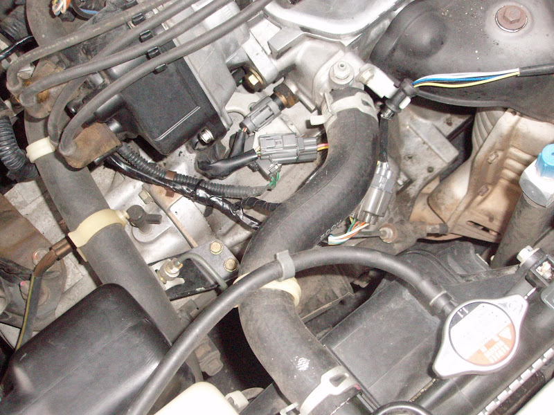
Here's a pic of the new harness connected to the 5-wire O2 sensor (can see the "shininess" of my new harness):
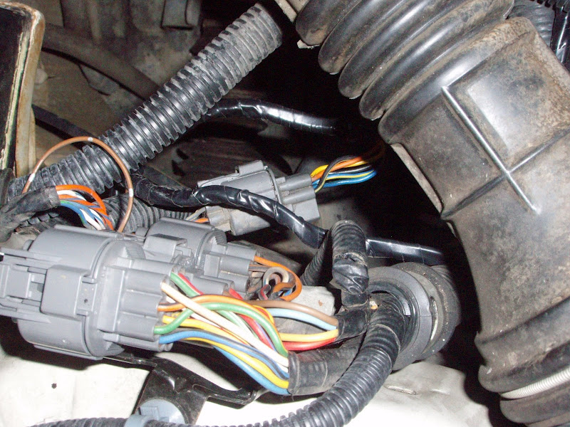
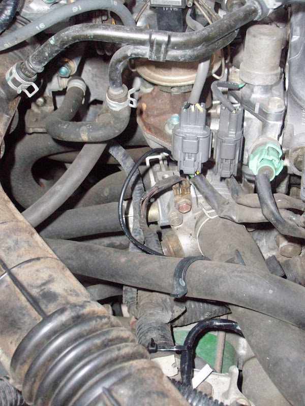
Here's a pic of the new harness connected near the shock tower:
Here's a pic of the ground point connection (G101):
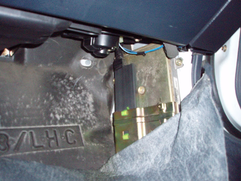
Within the passenger compartment, the ECU is behind the kick panel on the passenger side. I kinda struggled to get the carpet pulled back far enough to get to the ECU, but eventually got it out of the way enough to access the 4 connectors. Unfasten the connectors and pull the ECU free. I found it easiest to rotate the bottom of the ECU upward to the point where it was about horizontal, and then rotate the top downward. Disconnect the three connectors to free the ECU from the car and connect the Fed ECU.
Here's a pic of the ECU behind the kick panel; I had a hard time getting the carpet out of the way:
At this point (before bolting the new ECU in place), it might be a good idea to try starting the car and maybe even go for a drive to make sure everything's working as expected. If everything seems to be working fine,
Congratulations!! 
Button everything back up in the passenger compartment and enjoy the lean burn experience!