 12-06-2023, 08:53 PM
|
#11 (permalink)
|
|
Master EcoModder
Join Date: Aug 2012
Location: northwest of normal
Posts: 29,418
Thanks: 8,367
Thanked 9,128 Times in 7,537 Posts
|
I forget whether it was aerohead or I that found that picture. If I'd made it, it would look like this:
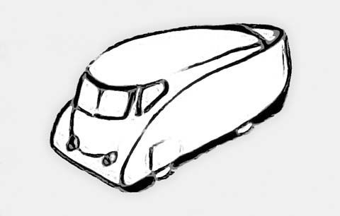
Slick top and a highly evolved underbody.
__________________
.
.Without freedom of speech we wouldn't know who all the idiots are. -- anonymous poster
___________________
.
.tragectory: Line goes down and to the right.
|
|
|

|
 Today Today
|
|
|
|
 Other popular topics in this forum...
|
|
|
|
 12-07-2023, 10:50 AM
|
#12 (permalink)
|
|
Master EcoModder
Join Date: Jan 2008
Location: Sanger,Texas,U.S.A.
Posts: 16,534
Thanks: 24,520
Thanked 7,438 Times in 4,818 Posts
|
' to improve aerodynamic'
Quote:
Originally Posted by yabert

Hi
I have a 1980 Vanagon electric powered by a 2017 Bolt EV powertrain.
Or if you prefer, I have a transgender Bolt EV 
I average 80 mpge (mpg equivalent) and I can easily do over 100-120 mpge in summer at lower speed.
Details here: https://www.thesamba.com/vw/forum/vi...737&highlight=
The pop top on our van is pure crap and I hate it so much. It's an old fiberglass piece of crap with holes, crack, etc.
To add, it is 3-4 inch's to low to stand up in the van without open it.
So I want to replace this pop top by a ridgid high roof top. 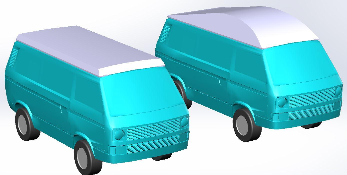
You can see the problem/challenge. How to improve energy consumption with a bigger front area?
I have to improve aerodynamic for sure and it's not so complex to do better than a stock Vanagon, but where can I start? |
If you're set on a 'fixed' roof, by 'eye-balling' what you've drawn, there's nothing wrong that I can discern, except for the sharp, longitudinal edges. You've taken care of the tumblehome already, but without softening the intersection between the top and sides, you'd be looking at a 13% drag penalty. It would require around an 80mm radius to mitigate vortex formation, the entire length of the roof, however, complicate the build by about 1,000%, requiring compound curvature, the absolutely-most-difficult shape to fabricate. The edge rounding would also benefit roll-moment during crosswind driving and gusts.
DON-BUR TEARDROP TRAILERS claims a 35.7% drag reduction @ 90-km/h, in spite of the aggravated frontal area, and the faster you drive, the greater the effect.
--------------------------------------------------------------------------------------
There's also a more efficient shape than this 'classic' teardrop bubble canopy/ blister, courtesy of Goro Tamai of MIT, who presented it in his 1999 book, THE LEADING EDGE, Figure 4.3.16, page- 195.
It's a reverse-bobbed, conjoined, double-canopy/blister, of Cd 0.045, instead of Cd 0.07, for the 'classic.'
It's pretty 'worthless' as far as outwards vision, but since that's not an issue up on the roof, it would be an option, and at 35% less drag, kinda compelling.
-------------------------------------------------------------------------------------
The Vanagon chassis gives you almost 4569mm of length to work with. Keeping standing headroom clearance to a minimum would provide quite a bit of 'fairing'/ 'canopy'/ 'blister' to work with. You'd go from zero, up a 17.5-degree incline, top out at the new height, along an arc, then just descend down the same 17.5-degree incline, blending into the metal roof.
-------------------------------------------------------------------------------------
Great project! Thanks for bringing attention to it here. My 1970 Transporter is now mumuring to me. 
__________________
Photobucket album: http://s1271.photobucket.com/albums/jj622/aerohead2/
|
|
|

|
 12-14-2023, 08:21 PM
|
#13 (permalink)
|
|
EcoModding Lurker
Join Date: Dec 2023
Location: Quebec
Posts: 23
Thanks: 0
Thanked 4 Times in 3 Posts
|
Quote:
Originally Posted by aerohead

you'd be looking at a 13% drag penalty. It would require around an 80mm radius to mitigate vortex formation, the entire length of the roof, however, complicate the build by about 1,000%,
|
Thanks for all details. I guess 13% penalty in nothing and don't worth the extra fabricating effort.
Quote:
|
You'd go from zero, up a 17.5-degree incline, top out at the new height, along an arc, then just descend down the same 17.5-degree incline, blending into the metal roof.
|
1-Is it possible to see this?
2-What about the other axes. I guess it's better to be smaller to the rear, but how to know the best shape?
3-How about the final transition ''blending into the metal roof''? Is the best shape go down at the rear, is it go straight (let say down 17.5°) or is it better to go parallel to road a bit like the rear of a Tesla Model 3?
I have all those question because I have limited aerodynamic experiment.
I think I can do something with Solidworks flow express. I don't know how it work and I don't know if this flow express have enough features to calculate the best shape I'm looking for. |
|
|

|
 12-15-2023, 01:19 AM
|
#14 (permalink)
|
|
Master EcoModder
Join Date: Aug 2012
Location: northwest of normal
Posts: 29,418
Thanks: 8,367
Thanked 9,128 Times in 7,537 Posts
|
Quote:
Of course it's fabricable. The question is more related to what is the good shape to fabricate.
....
Thanks for all details. I guess 13% penalty in nothing and don't worth the extra fabricating effort.
|
Your choice of materials and methods will determine how achievable a given shape is. aerohead's 80mm suggestion apparently is for the longitudinal edges. Were you to obtain a 6" aluminum irrigation pipe and cut it in thirds lengthwise, those rolled edges could become a cage with gaps to fill.
If you curve what have become long strips the angle widens from 120° toward what you require for tumblehome.
How tall are you? That would be a good starting point.
 https://www.thesamba.com/vw/gallery/pix/1134951.jpg
I don't know or care about Solidworks. Blender (currently 4.01) would allow you to import that JPG into an image plane so you could use NURBs Bézier curves or simple polygon extrusions for modeling. There is a simulation node editor in recent versions for CFD, but that [aways] beyond my pay grade.
Simplest: Two quadrilaterals and two triangles -- lots of tumblehome like the Cybertruck.
Next: Rolled edges with crescent and hourglass shapes to fill.
Most complex: Full compound curved, with cedar strip or stitch and glue canoe technique.
__________________
.
.Without freedom of speech we wouldn't know who all the idiots are. -- anonymous poster
___________________
.
.tragectory: Line goes down and to the right.
|
|
|

|
 12-15-2023, 03:40 PM
|
#15 (permalink)
|
|
EcoModding Lurker
Join Date: Dec 2023
Location: Quebec
Posts: 23
Thanks: 0
Thanked 4 Times in 3 Posts
|
Quote:
Originally Posted by freebeard

Your choice of materials and methods will determine how achievable a given shape
|
At the moment I want to stick with aluminum sheet. Strong, rigid, lightweight, laser cut, easy to weld, drill, etc.
Quote:
|
How tall are you? That would be a good starting point.
|
I'm 5' 9'', but in with any shape there is enough space. (1900mm = 6'3'')
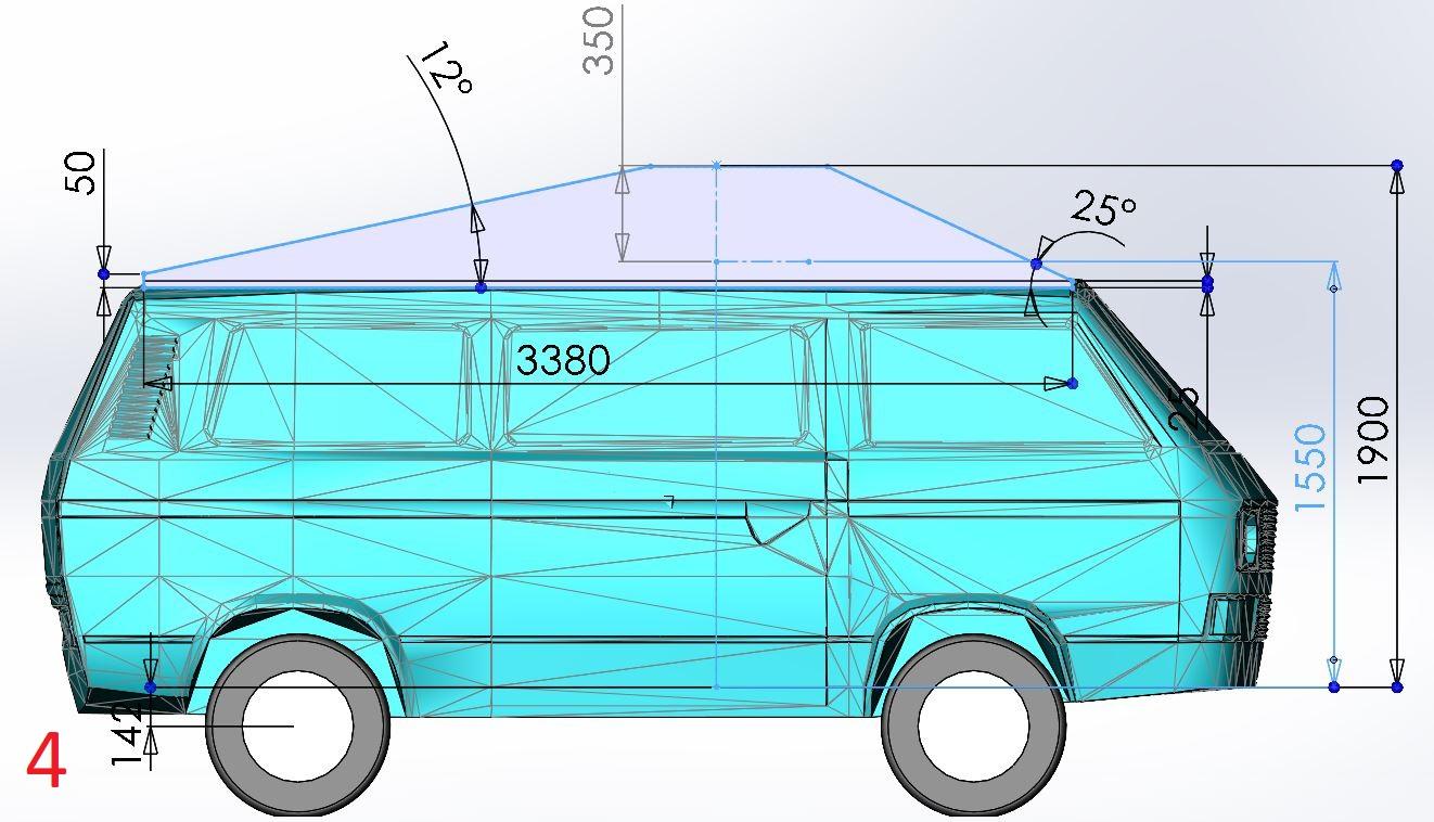
The challenge is to have space for extra bed to still be able to sleep 4 peoples (2 kids, 2 adults).
Let start with only 1 dimensions.
I create 4 shapes as you can see below. In my mind with limited knowledge about aero, the shape 1 is the best and give a lot of room in front.
But if I understand advice correctly, the shape 2 is the most aerodynamic.
What about shape 3. Perfect teardrop, no? The 45° almost match the windshield angle. Good, no?
And shape 4 is there to know if the big giant radius on top is important or if a flat can be ok.


|
|
|

|
|
The Following 2 Users Say Thank You to yabert For This Useful Post:
|
|
 12-15-2023, 04:18 PM
|
#16 (permalink)
|
|
Master EcoModder
Join Date: Aug 2012
Location: northwest of normal
Posts: 29,418
Thanks: 8,367
Thanked 9,128 Times in 7,537 Posts
|
#1 would be my choice. #2 interprets aerohead's suggestion, I'd like to see if he confirms it.
Maybe he will explain why having the peak be 30% back on the overall length is optimal.
Your constraint would be the location and size of the rooftop hatch opening. To preserve the bunks, are you going high-top or pop-up?
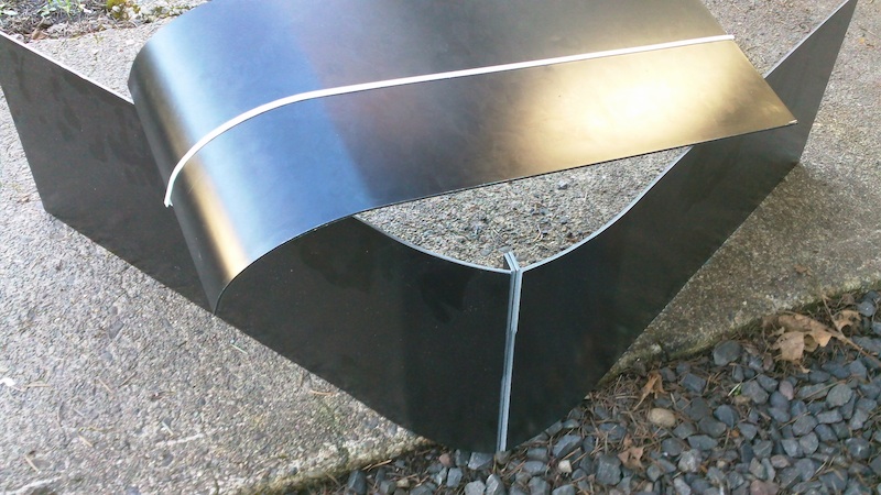
For material I like PolyMetal/Alumipanel composite sheet. Stiff as 5/8" plywood and prefinished.
__________________
.
.Without freedom of speech we wouldn't know who all the idiots are. -- anonymous poster
___________________
.
.tragectory: Line goes down and to the right.
|
|
|

|
 12-16-2023, 12:14 PM
|
#17 (permalink)
|
|
Master EcoModder
Join Date: Jan 2008
Location: Sanger,Texas,U.S.A.
Posts: 16,534
Thanks: 24,520
Thanked 7,438 Times in 4,818 Posts
|
'see this'
Quote:
Originally Posted by yabert

Thanks for all details. I guess 13% penalty in nothing and don't worth the extra fabricating effort.
1-Is it possible to see this?
2-What about the other axes. I guess it's better to be smaller to the rear, but how to know the best shape?
3-How about the final transition ''blending into the metal roof''? Is the best shape go down at the rear, is it go straight (let say down 17.5°) or is it better to go parallel to road a bit like the rear of a Tesla Model 3?
I have all those question because I have limited aerodynamic experiment.
I think I can do something with Solidworks flow express. I don't know how it work and I don't know if this flow express have enough features to calculate the best shape I'm looking for.
|
1) you've essentially depicted it in your #2 image, excepting that, you'd have a 2-D flow apparatus, instead of 3-D, with no facility for a '3D relieving effect', described by Goro Tamai.
2) as to 'best' shape, that would be the conjoined, nose-less, double-tailed, 3-D 'blister/ canopy', with a 100% 'aft-body', both in elevation and plan-view, however, that's off the table as far as your fabrication goes.
3) 'qualitativley', it could have 35% lower drag than the 'classic' bubble canopy, but since it's being used as a 2-D structure, it remains an unknown quantity.
--------------------------------------------------------------------------------------
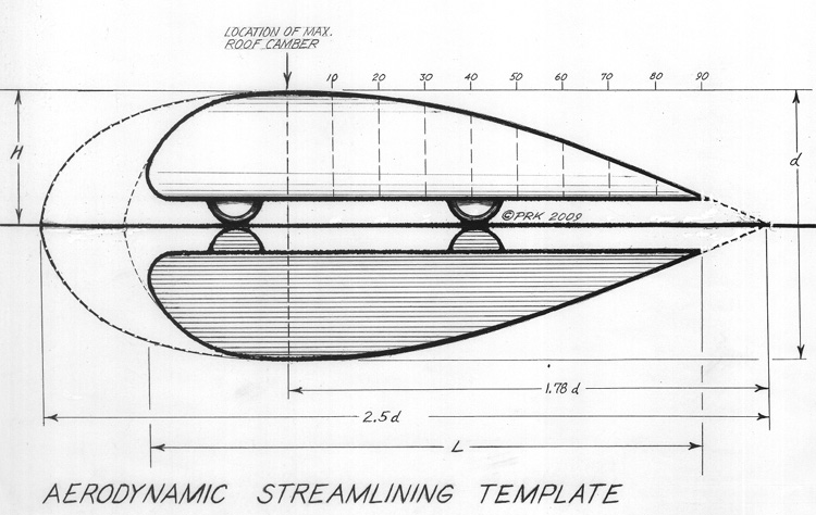
If we want to back-pedal a bit, we could discuss the 'two' Vanagons you're driving. In road vehicle aerodynamics, we must consider the 'form' of the vehicle's body, 'above' and 'below' the ground, in mirror image ground reflection, as it would appear in free flight.
Combining to two provides what the air 'sees.' We drive the 'right-side-up' version, while the air also sees the 'upside-down version.' ( this is built into the code of all CFD software ).
--------------------------------------------------------------------------------------
If you wanted, you could scale the Vanagon, with each roof mod to fit under the apex of the aerodynamic streamlining template gen-3 tool, here at the Aerodynamics Forum, and 'see' how it compares. ( if you watch the wind tunnel video of the Audi E-Tron GT, you'll see the Cd 0.04 streamline body of revolution which the 'template' is based upon. Hucho used it in his 1986 textbook, although it dates to the 19-teens, and is shared by Sighard Hoerner in his book, 'AERODYNAMIC DRAG', published in 1951, and 1965).
This contour/silhouette is a known quantity, and is presently used for the lowest drag concepts and production cars.
--------------------------------------------------------------------------------------
If I had the facility, I'd print out your CAD drawings and go ahead and do the comparisons.
--------------------------------------------------------------------------------------
The angled roof of the DON-BUR TEARDROP TRAILER channels the roof flow downwards into the base ( wake ), and although it may produce some vorticity, it doesn't appear to be a drag liability. So all of your 'aft-body' portions of the roof extension, in theory, should be okay.
-------------------------------------------------------------------------------------
You might consider fabricating a full-scale mockup for one of the 'teardrop' roofs out of 1/2-inch ( 13mm ) polyisocyanurate rigid foam insulation board and duct tape, then drive the 'transbolt' like you're going to, capture the 'miles/ kWh' from the 'guess-o-meter', then using what you've already tested, carefully deconstruct the roof, re-cut the sides, to create the 'double-tailed' #2 shape, tape the roof back on, and re-test at the same conditions, as best you can, and see if you can discern a 'winner.'
Think Flight has a great YouTube for his Subaru Impreza aero project, Gen-II, version-4 that you might get a kick out of .
--------------------------------------------------------------------------------------
if this takes, you're looking at an under-slung, add-on cargo pod, seen in 'Flying Wild Alaska'. The leading edge has little significance, whereas, the 'aft-body' is given a lot of attention.
https://www.bing.com/images/search?v...t=0&ajaxserp=0
__________________
Photobucket album: http://s1271.photobucket.com/albums/jj622/aerohead2/
Last edited by aerohead; 12-16-2023 at 12:34 PM..
Reason: add image link
|
|
|

|
 12-16-2023, 01:21 PM
|
#18 (permalink)
|
|
Master EcoModder
Join Date: Aug 2012
Location: northwest of normal
Posts: 29,418
Thanks: 8,367
Thanked 9,128 Times in 7,537 Posts
|
Quote:
In road vehicle aerodynamics, we must consider the 'form' of the vehicle's body, 'above' and 'below' the ground, in mirror image ground reflection, as it would appear in free flight.
Combining to two provides what the air 'sees.' We drive the 'right-side-up' version, while the air also sees the 'upside-down version.' ( this is built into the code of all CFD software ).
|
I don't pretend to understand this, but here's an illustration.
And here're two more hightops, my favorite is the Swedish military one:


__________________
.
.Without freedom of speech we wouldn't know who all the idiots are. -- anonymous poster
___________________
.
.tragectory: Line goes down and to the right.
|
|
|

|
 12-17-2023, 10:59 AM
|
#19 (permalink)
|
|
EcoModding Lurker
Join Date: Dec 2023
Location: Quebec
Posts: 23
Thanks: 0
Thanked 4 Times in 3 Posts
|
Quote:
Originally Posted by aerohead

You might consider fabricating a full-scale mockup for one of the 'teardrop' roofs out of 1/2-inch ( 13mm ) polyisocyanurate rigid foam insulation board and duct tape, then drive the 'transbolt' like you're going to, capture the 'miles/ kWh'
|
There is way to much others variables like air temperature, wind, etc, to end with interesting result doing this.
I know my power requirement in direct in my Vanabolt dash (like every Bolt).
At highway speed, on cruise control, this one can vary from 16 kW up to 50 kW for different reasons.
So I'm not interested to take huge amount of time doing foam prototype to have barely noticeable result or clearly wrong result.
My goal is simply to build (1 time) a high-top with a good shape who can potentially increase my range.
It will not be the perfect shape, but I'm trying to have as much information/knowledge as possible to not building something bad.
It seem like I will not find 3D flow simulators help here, but what can be a first ''accessible'' book to read about vehicle aerodynamic?
Accessible like I can understand at least 1/2 of what I read  |
|
|

|
 12-17-2023, 12:44 PM
|
#20 (permalink)
|
|
Master EcoModder
Join Date: Aug 2012
Location: northwest of normal
Posts: 29,418
Thanks: 8,367
Thanked 9,128 Times in 7,537 Posts
|
Quote:
|
It seem like I will not find 3D flow simulators help here, but what can be a first ''accessible'' book to read about vehicle aerodynamic?
|
As you say, the perfect is the enemy of the good.
If you were asking about help with CFD, that wasn't clear. There are threads here on the subject, and a Search field in upper left. If you want to read books, then search for Julian Edgar.
ecomodder.com/forum/showthread.php/new-amateur-aerodynamics-book
Quote:
New amateur aerodynamics book
Hello everyone - I have been given permission by the webmaster to spruik* my new book.
It's called the Amateur Car Aerodynamics Sourcebook.
Amazon have it on opening special at the moment - see Amazon.com: Amateur Car Aerodynamics Sourcebook: For everyone interested in road car aerodynamics (9781482735253): Julian Edgar: Books
The blurb says:
At last – a book for those who like to modify the aerodynamics of their road cars!
In this book author Julian Edgar explores a host of practical and low-cost techniques that you can do yourself without spending a lot of money or needing special facilities.
Section 1 introduces aerodynamic drag and lift. The language is simple and straightforward – but still includes concepts such as drag co-efficients, lift co-efficients and the different types of drag that affect road cars.
Section 2 is devoted to aerodynamic testing – directly measuring aerodynamic pressures, and seeing airflow patterns by the use of on-road wool-tuft testing.
Section 3, the largest part in the book, covers aerodynamic modification. Fitting vortex generators, testing different undertrays, reducing drag, using turning vanes in intercooler ducting – all are covered in detail. In addition, techniques are described for reducing wind noise, building an effective engine intake that breathes high-pressure cold air, siting bonnet vents in the correct location, and testing airflow through intercoolers.
With nearly 300 full-colour photos and diagrams, this book is practical and down to earth – and uses techniques able to be carried out on the road.
|
Else you could just take the profile you've drawn, maximize the tumblehome and radius the edge to 3-4" and be done.
*I have no idea what spruik means.
__________________
.
.Without freedom of speech we wouldn't know who all the idiots are. -- anonymous poster
___________________
.
.tragectory: Line goes down and to the right.
|
|
|

|
|