 09-09-2020, 01:21 PM
|
#21 (permalink)
|
|
Master EcoModder
Join Date: Jan 2008
Location: Sanger,Texas,U.S.A.
Posts: 16,503
Thanks: 24,517
Thanked 7,436 Times in 4,817 Posts
|
5% blockage ratio
Quote:
Originally Posted by JulianEdgar

1. I've already quoted the best reference that I am aware of on subsonic wind tunnel testing, and what it says about blockage factors.
'Low Speed Wind Tunnel Testing' (Barlow/Rae/Pope):
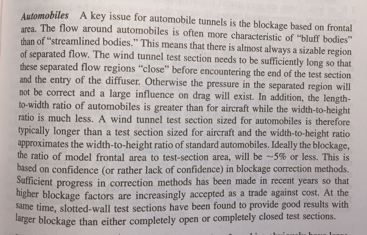
2. To suggest that car manufacturers, F1 teams (etc) build huge wind tunnels when there is no need to do so is simply not credible. |
Many readings of Hucho's chapter on wind tunnels helped me to understand the issue.
* On page 403 Hucho writes that the value of 5% is the limit for ' aircraft aerodynamics', not automobiles.
* On page 404, Hucho writes that ' condiderably higher blockage ratio is permissible for automotive aerodynamics.'
* On page 405, Hucho write that ' with streamlined walls the same result could be obtained with blockage of 20% as in test section with parallel walls with blockage of only 5%.'
* On page 407, Hucho writes that ' with 'adaptive-wall' tunnels with up to 30% blockage is fine.
* Later he writes that all these conditions are predicated upon the ability for yaw-testing, which is a different way to say that,with only zero-yaw measurements, even higher than 30% is okay.
* With a universal calibration model, Pininfarina, one of the smallest tunnels, returned values well within the standard deviation for a dozen or so tunnels tested worldwide.
* Adaptive-wall tunnels develop perfectly acceptable quanta, with blockage ratios of 30%. And this includes yaw testing.
* Curved-wall tunnels, as A2 and DARKO can provide perfectly fine numbers with even higher blockage ratios than 30%, due to the fact that everything is measured at zero yaw. There is no implication that results reflect anything but zero-yaw conditions.
* All this is predicated upon blockage correction factors developed from calibration testing in larger tunnels.
An example I gave you was the Toyota Prius.
1) We have a Cd for it from Toyota's wind tunnel
2) We have a Cd for it from A2. ( it was in the CAR and DRIVER 'Drag Queens' work which Don Sherman honcho'd ).
3) And we have a Cd for it from DARKO.
The Prius values, as a calibration model, allow us to 'adjust' measured coefficients between tunnels. An excepted practice within the industry.
4) Another wrench in the works is the fact that 'streamlined' cars upset the wind tunnel flow less than any other type during testing. They have a default safety margin designed in, as far as tunnel flow perturbation is concerned.
5) The other thing is that, the absolute values aren't as important as the trends in measurements, when limiting testing to a single tunnel as we did with Spirit. I could have done it all at A2. If I lived in Japan, I could have done all the work with the Toyota facility.
6) When you take all the conditions as a whole, a different picture emerges than one demanding a 5% blockage ratio. It's just not a universal absolute.
-------------------------------------------------------------------------------------
F1 is a multi-billion Euro / Dollar entertainment enterprise. It's a culture unto itself. Every trick in the book will be used to cheat within the rule book, to pull off a win. They're not going to leave any hypotheses untested. However that doesn't necessarily mean that there'll be any trickle-down technology useful in a passenger car. The tax code allows all expenses to be written off. And with millions in sponsor funding, it's skies the limit!
__________________
Photobucket album: http://s1271.photobucket.com/albums/jj622/aerohead2/
Last edited by aerohead; 09-11-2020 at 02:13 PM..
Reason: add data
|
|
|

|
 Today Today
|
|
|
|
 Other popular topics in this forum...
|
|
|
|
|
09-09-2020, 04:43 PM
|
#22 (permalink)
|
|
Banned
Join Date: Nov 2017
Location: Australia
Posts: 2,060
Thanks: 107
Thanked 1,608 Times in 1,137 Posts
|
Quote:
Originally Posted by aerohead
1) I'm not interested.If you are, do your own work.You talk of wings. For wings, the plan-view area of chord and span is used.
|
Cars use frontal area in the calculation of coefficients of drag and lift. You were attempting to muddy the water by using plan area not frontal area.
Quote:
|
2-3) The template was created to serve as a Go NoGo. It's derived from technology developed in the 1920s by NACA ( NASA). Its contour is incapable of producing flow separation ( that's why you'd want to use it).
|
Typical Aerohead non sequitur. I agree that the template (in 3D) is unlikely to have flow separation. That does not automatically lead to it being the best shaped body to use. A dog has four legs. Not all animals with four legs are dogs.
Quote:
|
Your tuft study does not have scientific rigor. It's fraught with shortcomings. Automakers don't use it.
|
Are you serious? Carmakers have used tuft testing for getting on for a century. Every single professional aerodynamicist who reviewed my book complimented me on the quality of the tuft testing I show. One said it was the clearest he'd ever seen. Another Formula 1 aerodynamicist told me that only people who don't know anything about car aero deride tuft testing. Here's an example of a carmaker not using it:

Quote:
4-5-6) Sometimes you appear to be obsessed with lift issues. Given the lift values reported for the Cadillac, Hucho's non-concern with lift was only reinforced. If you're a Princess and can feel a pea under a stack of mattresses, that's your problem. Lift is not associated with attached flow.
|
I am not obsessed with lift. It's just that it doesn't make good sense to utterly ignore it, as you do.
Lift is not associated with attached flow? You really believe that? Honestly, if you do, that is about a fundamental misunderstanding of aerodynamics as it's possible to get. Words fail me.
Quote:
|
* revisit your polar diagrams for wing sections.( A. Silverstein, NACA Report 502, p. 15, 1934 will be a revelation ).
|
The report has only 13 pages.
Quote:
|
* Hucho, p. 122 ( aspect ratio )
|
Aspect ratio is not relevant here. On the basis of what two professional car aerodynamicists have detailed to me, the description here of the relationship between induced drag and lift is now well outdated. (But from what I understand, this is an area of some disagreement between aerodynamicists.)
Quote:
|
* Hucho, p. 151, Fig. 4.54 (attached flow= lower lift)
|
Fig 4.54 does not mention lift. Fig 4.55 does though. It shows exactly what I have stated many times. Lift is higher with a fastback shape than a squareback shape. In fact, it's such a clear diagram of what really happens, here it is:

As this diagram so clearly shows, I am afraid your understanding is completely backwards.
Quote:
|
* Hucho, p. 217, Fig. 5.4, RAE 101 aerofoil @ 4-degrees offset flow pressure distribution, both sides.
|
Um, Fig 5.4 is showing aerodynamic side forces, not lift/downforce. Did you read the text?
Quote:
|
* Hucho, p. 282, Fig. 7.34 ( attached flow = lower lift )
|
This diagram shows the presence of a spoiler that causes earlier separation, not better flow attachment. That's exactly what I wrote in my book, and when reviewing this part, Dr Thomas Wolf (the current head of Porsche aerodynamics) agreed with my analysis. But hey, what would he know?
So what I am finding, and as someone else here identified a while ago, is that when I spend the time to look up each of the references you cite, you are very often misquoting and/or misunderstanding them.
Last edited by JulianEdgar; 09-09-2020 at 05:21 PM..
Reason: typos
|
|
|
|
|
The Following User Says Thank You to JulianEdgar For This Useful Post:
|
|
|
09-09-2020, 05:55 PM
|
#23 (permalink)
|
|
Master EcoModder
Join Date: Jan 2008
Location: Sanger,Texas,U.S.A.
Posts: 16,503
Thanks: 24,517
Thanked 7,436 Times in 4,817 Posts
|
attempting
Quote:
Originally Posted by JulianEdgar
Cars use frontal area in the calculation of coefficients of drag and lift. You were attempting to muddy the water by using plan area not frontal area.
Typical Aerohead non sequitur. I agree that the template (in 3D) is unlikely to have flow separation. That does not automatically lead to it being the best shaped body to use. A dog has four legs. Not all animals with four legs are dogs.
Are you serious? Carmakers have used tuft testing for getting on for a century. Every single professional aerodynamicist who reviewed my book complimented me on the quality of the tuft testing I show. One said it was the clearest he'd ever seen. Another Formula 1 aerodynamicist told me that only people who don't know anything about car aero deride tuft testing. Here's an example of a carmaker not using it:
I am not obsessed with lift. It's just that it doesn't make good sense to utterly ignore it, as you do.
Lift is not associated with attached flow? You really believe that? Honestly, if you do, that is about a fundamental misunderstanding of aerodynamics as it's possible to get. Words fail me.
The report has only 13 pages.
Aspect ratio is not relevant here. On the basis of what two professional aerodynamicists have detailed to me, the description here of relationship between induced drag and lift now well outdated. (But from what I understand, this is an area of some disagreement between aerodynamicists.)
Fig 4.54 does not mention lift. Fig 4.55 does though. It shows exactly what I have stated many times. Lift is higher with a fastback shape than a squareback shape. In fact, it's such a clear diagram of what really happens, here it is:
As this diagram so clearly shows, I am afraid your understanding is completely backwards.
Um, Fig 5.4 is showing aerodynamic side forces, not lift/downforce. Did you read the text?
This diagram shows the presence of a spoiler that causes earlier separation, not better flow attachment. That's exactly what I wrote in my book, and when reviewing this part. Dr Thomas Wolf (the current head of Porsche aerodynamics) agreed with my analysis. But hey, what would he know?
So what I am finding, and as someone else here identified a while ago, is that when I spend the time to look up each of the references you cite, you are very often misquoting and/or misunderstanding them. |
* Don't tell me what I was attempting.
* You brought up wings.
* I used what aeronautical engineers use.
* As to the template is 3-D, I'm only saying what Hummel page 57,59,61, Table 2.1, Hucho page 107, 117,119, 141, 160, 199, 200, 202, 203, 209, Daugherty and Franzini ( page- 295, figure 10.10, Page 297, page 315 ), and the others say, it's the 'OPTIMUM' shape for low drag.
* I don't see tufts in contemporary wind tunnel testing by manufacturers.
* I could care less about Formula-1.
* Hucho, a PhD mechanical engineer, who ran the VW climatic wind tunnel for a decade.
* Nowhere in Hucho's text ( Schenkel, Ohtani et al., Buchheim et al.,etc. ) did I find a rear spoiler application which was NOT being applied to a car without separation, except for like the C-11 III, which was a 250-mph record car, or full-blown race cars, which are nor germane to passenger cars. Even in the section on high-performance sports cars and race cars he published, on page 281, that in the absence of a elevated tail, ' it is also possible to use a spoiler, the decisive feature being the relative height of separation in relation to the rest of the body.' He's not installing a spoiler on a car with 'attached flow', but quite the contrary.
* When your Porsche 911 Carrera was sold in the USA, the national speed limit was 55-miles per hour. At that speed, your Porsche developed 19-pounds lift. This nay have something to do with Hucho's cool handling of the issue.
* You like to imply instability in the 'template.' Bring your bona-fides.
* ROAD & TRACK measured the rear lift of the Volkswagen 1600 Squareback at 70-pounds at 100-mph. The Karmann -Ghia was also 70-pounds. The Beetle had zero rear lift. The original Porsche 912 / 911 had 59.6-pounds rear lift, a little short of the Squareback.
I gave you a couple lift table references which indicate that lift is a function of separation, not attached flow. The trends are clearly delineated. And oddly enough, spoilers added to many high-end sports cars ascend to the contour of the template exactly. The Dodge Viper Coupe and Shelby Daytona Coupe are two which immediately come to mind. From their rear contours, neither car would be capable of attached flow in the proper sense of the definition.
* The caveat for lift associated with attached flow would be limited to 'track' cars, with which splitters, spoilers, or wings are added for downforce, with little added mass penalty to acceleration and braking. Again, that would not be germane to passenger cars and 'normal' driving.
* There's another issue with lift which has to do with premature flow separation. Like on the Porsche Macan, Cayenne, that whole genre of SUVs, Jaguar's I-Pace. By mutilating the roof with the 'raked-roof,' they're removing roof which could otherwise be providing gradual pressure rise, no lift, and lower drag. When Audi's E-Tron 'Sportback' comes out, see if it's rear lift isn't lower than its stablemate. Its got 20-counts less drag just from the shape.
I'm going to sign off here ,then look at your Amazon image.
__________________
Photobucket album: http://s1271.photobucket.com/albums/jj622/aerohead2/
|
|
|
|
|
09-09-2020, 06:06 PM
|
#24 (permalink)
|
|
Banned
Join Date: Nov 2017
Location: Australia
Posts: 2,060
Thanks: 107
Thanked 1,608 Times in 1,137 Posts
|
Fact 1: Aerohead said:
Quote:
Originally Posted by aerohead
* Hucho, p. 151, Fig. 4.54 (attached flow= lower lift)
|
Fact 2: Here is the diagram to which I assume Aerohead refers (Fig 4.54 has nothing to do with lift, but 4.55 does):
Fact 3: This diagram shows exactly the opposite of what Aerohead constantly argues! As you'd expect, it shows that a fastback has far more lift than a square back. The transition to lower lift occurs when the flow separates. What a surprise (not).
Fact 4: Aerohead has not bothered to address this massive misunderstanding that he constantly displays.
I strongly suggest that rather than accepting the references Aerohead nominates, people actually check them. When I spend the time to look up each of the references Aerohead cites, he is - more often than not - misquoting and/or misunderstanding them.
|
|
|
|
|
The Following User Says Thank You to JulianEdgar For This Useful Post:
|
|
|
09-09-2020, 06:20 PM
|
#25 (permalink)
|
|
Master EcoModder
Join Date: Jan 2008
Location: Sanger,Texas,U.S.A.
Posts: 16,503
Thanks: 24,517
Thanked 7,436 Times in 4,817 Posts
|
fastback / squareback
Quote:
Originally Posted by JulianEdgar
Cars use frontal area in the calculation of coefficients of drag and lift. You were attempting to muddy the water by using plan area not frontal area.
Typical Aerohead non sequitur. I agree that the template (in 3D) is unlikely to have flow separation. That does not automatically lead to it being the best shaped body to use. A dog has four legs. Not all animals with four legs are dogs.
Are you serious? Carmakers have used tuft testing for getting on for a century. Every single professional aerodynamicist who reviewed my book complimented me on the quality of the tuft testing I show. One said it was the clearest he'd ever seen. Another Formula 1 aerodynamicist told me that only people who don't know anything about car aero deride tuft testing. Here's an example of a carmaker not using it:
I am not obsessed with lift. It's just that it doesn't make good sense to utterly ignore it, as you do.
Lift is not associated with attached flow? You really believe that? Honestly, if you do, that is about a fundamental misunderstanding of aerodynamics as it's possible to get. Words fail me.
The report has only 13 pages.
Aspect ratio is not relevant here. On the basis of what two professional car aerodynamicists have detailed to me, the description here of the relationship between induced drag and lift is now well outdated. (But from what I understand, this is an area of some disagreement between aerodynamicists.)
Fig 4.54 does not mention lift. Fig 4.55 does though. It shows exactly what I have stated many times. Lift is higher with a fastback shape than a squareback shape. In fact, it's such a clear diagram of what really happens, here it is:
As this diagram so clearly shows, I am afraid your understanding is completely backwards.
Um, Fig 5.4 is showing aerodynamic side forces, not lift/downforce. Did you read the text?
This diagram shows the presence of a spoiler that causes earlier separation, not better flow attachment. That's exactly what I wrote in my book, and when reviewing this part, Dr Thomas Wolf (the current head of Porsche aerodynamics) agreed with my analysis. But hey, what would he know?
So what I am finding, and as someone else here identified a while ago, is that when I spend the time to look up each of the references you cite, you are very often misquoting and/or misunderstanding them. |
Look at the angles represented in the table. They're all in separated flow.
Drag minimum for the fastback occurs at 15-degrees and you'll see it's lower lift on the other table I believe ( I didn't bring the book with me).Lift minimum is at zero-degrees and full-attachment on the roof.
The lift over the slope is a function of low pressure due to premature separation,closer to the roof location of lowest pressure ( just ahead of the windshield header ), and the vortex train.
* On the NACA Report, I wanted you to see the polar diagram for the Clark-Y aerofoil, and it's zero-lift at negative 5.6-degrees angle-of-attack, negative lift at negative 8,2 degrees angle-of-attack, and maximum lift at positive 15.6 -degrees angle-of-attack. Daugherty and Franzini published that it's 'essential' that this relationship be understood.
* On aspect ratio, one needs to understand that on a car we're looking at 0.3, and on say, a Piper Cherokee, it's 6.0. It is relevant.
* I couldn't link to you Amazon reference. I'm not much with computers.
__________________
Photobucket album: http://s1271.photobucket.com/albums/jj622/aerohead2/
|
|
|
|
|
09-09-2020, 06:42 PM
|
#26 (permalink)
|
|
Banned
Join Date: Nov 2017
Location: Australia
Posts: 2,060
Thanks: 107
Thanked 1,608 Times in 1,137 Posts
|
Quote:
Originally Posted by aerohead
Look at the angles represented in the table. They're all in separated flow.
|
[Groan]
No they're not...
I don't quite believe that I am having to do this but here's the rest of the diagram.

1. Note how the wake is shown behind the two shapes.
2. Note how the wake is larger on 'A', indicated in the graph by the solid dots.
3. Note how the waker is smaller on 'B', indicated in the graph by the hollow dots.
4. Note therefore that there is attached flow in 'B'.
Honestly, this is becoming quite ridiculous.
|
|
|
|
|
The Following User Says Thank You to JulianEdgar For This Useful Post:
|
|
|
09-09-2020, 08:42 PM
|
#27 (permalink)
|
|
Banned
Join Date: Nov 2017
Location: Australia
Posts: 2,060
Thanks: 107
Thanked 1,608 Times in 1,137 Posts
|
Quote:
Originally Posted by aerohead
* On the NACA Report, I wanted you to see the polar diagram for the Clark-Y aerofoil, and it's zero-lift at negative 5.6-degrees angle-of-attack, negative lift at negative 8,2 degrees angle-of-attack, and maximum lift at positive 15.6 -degrees angle-of-attack.
|
You keep talking about wing profiles having the ability to develop zero lift at certain angles of attack. That's fine - there's plenty of data that shows that. Trouble is, it's another of your argument red herrings.
For example, let's give The Template a negative 5.6 degree angle of attack (as you nominate for the Clark Y) and then let's add a suitable underfloor profile (red).

I'd be pretty confident that lift would now be waaaay down. Trouble is, it's also now a completely different shape...
|
|
|
|
|
The Following User Says Thank You to JulianEdgar For This Useful Post:
|
|
|
09-11-2020, 11:45 AM
|
#28 (permalink)
|
|
Master EcoModder
Join Date: Jan 2008
Location: Sanger,Texas,U.S.A.
Posts: 16,503
Thanks: 24,517
Thanked 7,436 Times in 4,817 Posts
|
nothing to do
Quote:
Originally Posted by JulianEdgar
Fact 1: Aerohead said:
Fact 2: Here is the diagram to which I assume Aerohead refers (Fig 4.54 has nothing to do with lift, but 4.55 does):
Fact 3: This diagram shows exactly the opposite of what Aerohead constantly argues! As you'd expect, it shows that a fastback has far more lift than a square back. The transition to lower lift occurs when the flow separates. What a surprise (not).
Fact 4: Aerohead has not bothered to address this massive misunderstanding that he constantly displays.
I strongly suggest that rather than accepting the references Aerohead nominates, people actually check them. When I spend the time to look up each of the references Aerohead cites, he is - more often than not - misquoting and/or misunderstanding them.
|
In Figure 4.54, at the bottom of the table you can see the separation-induced vortex-drag increasing with the down-slope angle, up until 'burst' occurs. This is very important with respect to cars like the 911/ 912.
--------------------------------------------------------------------------------------
In Figure 4.55, all the data presented is for separated flow and high vortex-drag. The drag minimum, and lower lift occurred at 15-degrees. You can clearly see the trend line down towards the 15-degree point on the table. And above, in Figure 4.54, you can actually see what the vortex-drag component is @ 15-degrees. The lowest lift occurred at the original roof contour ( actually on the 'template', but at high truncation ).
-------------------------------------------------------------------------------------
With respect to fastback rear lift exceeding notchback rear lift, some counterfactual evidence is presented in Hucho's Figure 5.9, on page 221.
* A close examination of the lift table reveals a CL 0.4500 for the fastback, while the notchback version of the same car is CL 0.5085.
* The lift relationship for the two cars remains until 29-degrees of yaw, where they're identical rear lift values, then the fastback overtakes the notchback as the table ends, at 30-degrees yaw.
-------------------------------------------------------------------------------------
The squareback shown, registered CL 0.2390, however this car is a Type 36, not a Type 31, as with the upper two cars. It, technically would not be an apples-to-apples comparison.
--------------------------------------------------------------------------------------
The table also provides the asymptotes for each car's maximum crosswind CL.
__________________
Photobucket album: http://s1271.photobucket.com/albums/jj622/aerohead2/
|
|
|
|
|
09-11-2020, 12:06 PM
|
#29 (permalink)
|
|
Master EcoModder
Join Date: Jan 2008
Location: Sanger,Texas,U.S.A.
Posts: 16,503
Thanks: 24,517
Thanked 7,436 Times in 4,817 Posts
|
wake is smaller on 'B'
Quote:
Originally Posted by JulianEdgar
[Groan]
No they're not...
I don't quite believe that I am having to do this but here's the rest of the diagram.
1. Note how the wake is shown behind the two shapes.
2. Note how the wake is larger on 'A', indicated in the graph by the solid dots.
3. Note how the waker is smaller on 'B', indicated in the graph by the hollow dots.
4. Note therefore that there is attached flow in 'B'.
Honestly, this is becoming quite ridiculous. |
--------------------------------------------------------------------------------------
1) Again, you completely miss the context of the 'small' wake.
2) This wake is not an artifact of slow, gradual, pressure rise,high base pressure, free of separation - induced,high-drag, three-dimensional, attached longitudinal vortex trains.
3) You've fallen into exactly the same fallacy as with the Porsche 911.
4) It is separation-induced, high-drag vortices which create the downwash which holds the flow down the slope. It violates everything Hucho advocates with respect to streamlining, and why he reasons that streamlined half-bodies are the direction for low drag. ( page-15,16,39,109,117,118,142,144,155,169,175,200,201, and 210.
__________________
Photobucket album: http://s1271.photobucket.com/albums/jj622/aerohead2/
|
|
|
|
|
09-11-2020, 12:47 PM
|
#30 (permalink)
|
|
Master EcoModder
Join Date: Jan 2008
Location: Sanger,Texas,U.S.A.
Posts: 16,503
Thanks: 24,517
Thanked 7,436 Times in 4,817 Posts
|
'there's plenty of data that shows that.'
Quote:
Originally Posted by JulianEdgar
You keep talking about wing profiles having the ability to develop zero lift at certain angles of attack. That's fine - there's plenty of data that shows that. Trouble is, it's another of your argument red herrings.
For example, let's give The Template a negative 5.6 degree angle of attack (as you nominate for the Clark Y) and then let's add a suitable underfloor profile (red).
I'd be pretty confident that lift would now be waaaay down. Trouble is, it's also now a completely different shape... |
--------------------------------------------------------------------------------------
* Finally, after a year or so, you publicly announce that all wings are capable of zero-lift. This is real progress. Thank you!
* I've provided the underbody profile. It's basically flat until the long, 2.8-degree diffuser completes the belly. The rest of what you see is the wheel fairing package. SAE 'approach', breakover', and 'departure' angle limits for a passenger vehicles are respected.
* As to a car-width 'wing section' for an automobile, this was tested by Kamm at FKFS and returned Cd 0.21 as a lange-heck.
* Adding tumblehome reduced the drag to Cd 0.1764.
* Adding body camber and boat-tailing produced Cd0.1481.
* And the long diffuser takes it to Cd 0.1231 ( Template car measured Cd 0.1201 with crappy wheel fairings ).
* In front elevation, the 'template' car approximates a semicircle in cross-section. There isn't a flat surface on the car anywhere. It's all compound surfaces.
* A couple of 'wingtips' joined together would be a more accurate characterization of the form. It's a streamline half-body.
* The sides mirror the top contour.
* Pressures alongside are very close to up above.
* There is no vorticity.
* Boat-tailing creates continuous cross-sectional contraction and surface area reduction, all the way to essentially zero, over the latter 2/3rds of body length. That doesn't make for a very good 'wing.'
* Passive pressure acting over the aft-body would be at the highest positive values observable.
* Active suspension and reduced ground clearance offers opportunities.
* Active suspension offers body inclination opportunities.
* The tail can be 'deployable' as with Hucho's Figure 8.63.
* Static wheel loading due to travel weight may make the whole 'lift' issue a non-starter.
-------------------------------------------------------------------------------------
As a piece of crap, Spirit is quite stable at 108- mph. In crosswind, exposed ,on an elevated interstate highway. With wind tunnel tuning I would venture that it could perform any 'normal' driving functions without drama.
__________________
Photobucket album: http://s1271.photobucket.com/albums/jj622/aerohead2/
|
|
|
|
|


