 06-08-2016, 05:46 PM
|
#1 (permalink)
|
|
EcoModding Lurker
Join Date: Mar 2015
Location: -
Posts: 30
Thanks: 3
Thanked 12 Times in 11 Posts
|
NACA duct or scoop
Found this:
NACA Duct vs. Scoops | Ivanitski
Too bad there are no drag numbers.
|
|
|

|
|
The Following User Says Thank You to gafhj For This Useful Post:
|
|
 Today Today
|
|
|
|
 Other popular topics in this forum...
|
|
|
|
 06-08-2016, 06:19 PM
|
#2 (permalink)
|
|
Master EcoModder
Join Date: Jan 2008
Location: Sanger,Texas,U.S.A.
Posts: 16,433
Thanks: 24,481
Thanked 7,411 Times in 4,801 Posts
|
NACA vs SCOOP
I've no specific drag breakdowns for either.
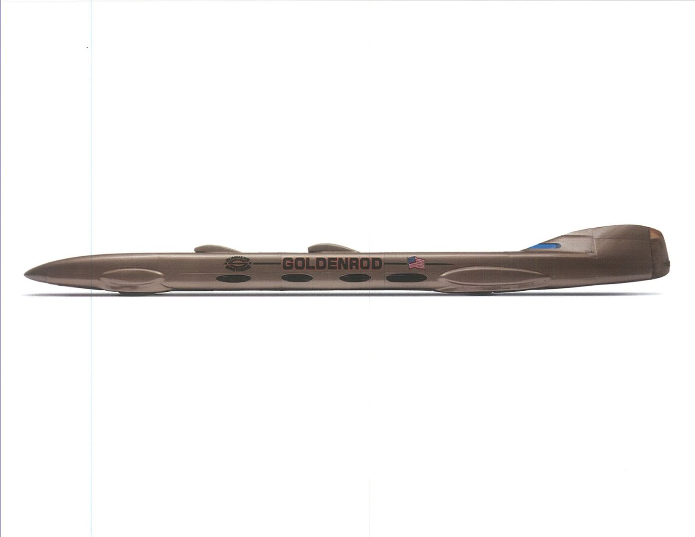
Walter Korff chose Bauman scoops for the Summers Brothers Goldenrod,Cd 0.117.
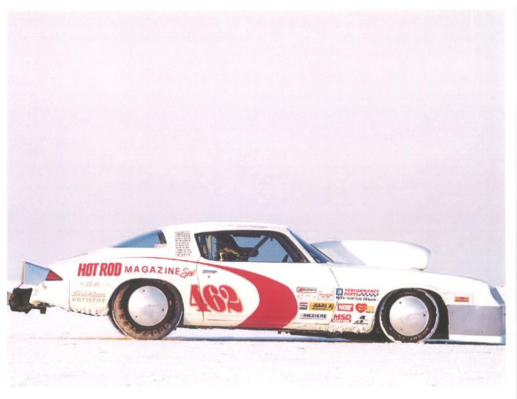
This Pro Comp hood scoop reduced require horsepower at 200-mph by 150-hp,compared to the exposed 671 Supercharger.
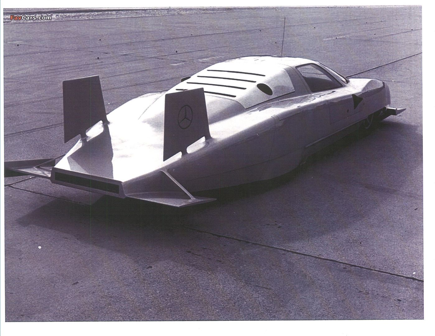
Daimler-Benz chose NACA submerged inlets for their C111 III (Cd 0.178 w/o wings).
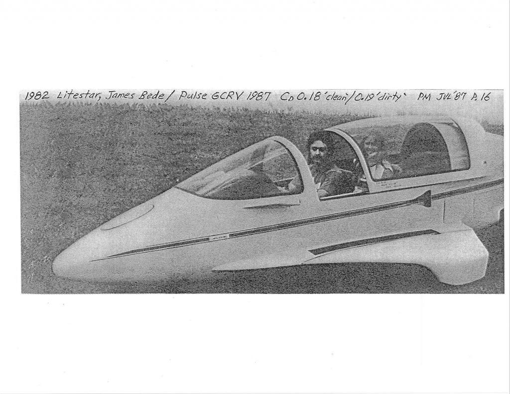
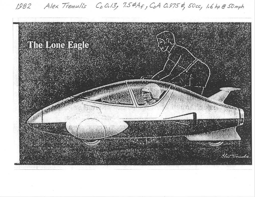
Aeronautical engineer,James Bede chose NACA for his road-going fuselage.
ditto,Alex Tremulis,
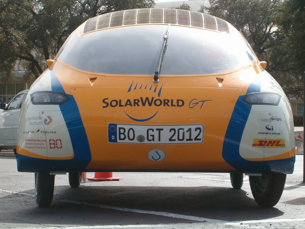
ditto,Bochum University
Chevrolet wanted to use them for the new Corvette but didn't have enough interior volume inside the quarter panels for their particular architecture,so they just did the best with what they had.
I suspect that the decision comes down to interior packaging constraints.
I suspect that the NACA design is ideal,but doesn't always fit with respect to inflexible project realities.
__________________
Photobucket album: http://s1271.photobucket.com/albums/jj622/aerohead2/
Last edited by aerohead; 06-08-2016 at 06:34 PM..
Reason: add image
|
|
|

|
|
The Following 2 Users Say Thank You to aerohead For This Useful Post:
|
|
 06-10-2016, 10:50 AM
|
#3 (permalink)
|
|
Master EcoModder
Join Date: Jul 2011
Location: Ann Arbor, Michigan
Posts: 4,196
Thanks: 135
Thanked 2,819 Times in 1,979 Posts
|
Thank you for posting the article.
I'm still looking for an image of a 1950's experimental US jet fighter along the Demon/Voodoo lines. It had NCAC air intake inlets.
Posted it a few years ago and now cannot find it.
__________________
George
Architect, Artist and Designer of Objects
2012 Infiniti G37X Coupe
1977 Porsche 911s Targa
1998 Chevy S-10 Pick-Up truck
1989 Scat II HP Hovercraft
You cannot sell aerodynamics in a can............
|
|
|

|
 01-10-2021, 11:28 AM
|
#4 (permalink)
|
|
Ultimate Fail
Join Date: Feb 2008
Location: Austin,Texas
Posts: 3,585
Thanks: 2,872
Thanked 1,121 Times in 679 Posts
|
How important is following a template to the function of a NACA duct ?
I plan on adding some to my car, but am limited on space.
I see some templates online that show a 10 to 6 ratio.
If I go with a 'fatter' 10 to 7.5, will it decrease the efficiency ?
|
|
|

|
 01-10-2021, 04:47 PM
|
#5 (permalink)
|
|
Banned
Join Date: Nov 2017
Location: Australia
Posts: 2,060
Thanks: 107
Thanked 1,608 Times in 1,137 Posts
|
Quote:
Originally Posted by Cd

How important is following a template to the function of a NACA duct ?
I plan on adding some to my car, but am limited on space.
I see some templates online that show a 10 to 6 ratio.
If I go with a 'fatter' 10 to 7.5, will it decrease the efficiency ?
|
I've never used nor designed a NACA duct, so I don't have personal experience.
In my references, Tune to Win (Carroll Smith) has detailed diagrams showing what criteria a NACA duct needs to conform with to be effective.


He also states that for them to work:
- they must be made very closely to the design shown above
- they must be in attached flow
- the boundary layer needs to be thin
- they need to be located parallel to the local airflow
He also adds that:
- the angle of the ramp floor should be a max of 10 degrees
- the ratio of duct depth to duct width should be as high as practical (deep ducts)
- there must be a radiused lip at the rear of the skin opening
- the duct corners must be kept square
|
|
|

|
|
The Following 2 Users Say Thank You to JulianEdgar For This Useful Post:
|
|
 01-10-2021, 06:07 PM
|
#6 (permalink)
|
|
Ultimate Fail
Join Date: Feb 2008
Location: Austin,Texas
Posts: 3,585
Thanks: 2,872
Thanked 1,121 Times in 679 Posts
|
Thanks guys !
Here is what I have so far.
There will be three sizes, and they range from looking correct, to looking a bit too fat.
This picture of the ducts shows three variations of the duct on a jet engine, and I'm inspired by the one on the bottom right. ( the 'fattest' one )
|
|
|

|
 01-10-2021, 08:01 PM
|
#7 (permalink)
|
|
Ultimate Fail
Join Date: Feb 2008
Location: Austin,Texas
Posts: 3,585
Thanks: 2,872
Thanked 1,121 Times in 679 Posts
|
So are the fatter style ducts ( see photo attached in post above ) less effective ?
By the looks of it, the fatter designs seem to be shallower.
|
|
|

|
|
The Following User Says Thank You to Cd For This Useful Post:
|
|
 01-10-2021, 08:33 PM
|
#8 (permalink)
|
|
Banned
Join Date: Nov 2017
Location: Australia
Posts: 2,060
Thanks: 107
Thanked 1,608 Times in 1,137 Posts
|
Where are you planning on placing them and what is their function?
|
|
|

|
 01-10-2021, 09:05 PM
|
#9 (permalink)
|
|
Ultimate Fail
Join Date: Feb 2008
Location: Austin,Texas
Posts: 3,585
Thanks: 2,872
Thanked 1,121 Times in 679 Posts
|
Quote:
Originally Posted by JulianEdgar

Where are you planning on placing them and what is their function?
|
Sorry for the delay.
I plan on placing them on my kammback.
They will probably increase drag more than anything, but I'm willing to add them even if they do only that, because I like the look. ( I can easily cover over them )
I plan to test how they work later.
I'd like to see if I can channel some of the air inside the kammback to create less vaccum back there.
I know that the amount of air the ducts are going to push out is most likely like blowing with your mouth on a raging forest fire. ( useless )
I plan to add flexible ducting leading from the NACA ducts to the middle of the dead zone, but for now, will just have them open. The air will exit under the kammback, instead of over the top.
Besides liking the look of the NACA ducts, I think they may be able to serve yet another function.
I have seen how reverse NACA ducts work, and they would help to relieve trapped air from inside the kammback if there is a windstorm.
Already, I have an open area in the kammback where my 3rd brake light is, and it actually seems to work to relieve trapped air. The kammback has survived some pretty heavy gusts ( 30 mph ? ) and not ripped off. |
|
|

|
|
The Following User Says Thank You to Cd For This Useful Post:
|
|
 01-10-2021, 09:32 PM
|
#10 (permalink)
|
|
Banned
Join Date: Nov 2017
Location: Australia
Posts: 2,060
Thanks: 107
Thanked 1,608 Times in 1,137 Posts
|
That's an interesting idea but my guess is that, back there, the boundary layer will be too thick for them to work in terms of pushing air into the wake. With the low pressure wake, I imagine air will flow through the ducts, but not change the wake pressure.
(And I know people here call them that, but that's not a Kammback. Partial box cavity?)
|
|
|

|
|
The Following User Says Thank You to JulianEdgar For This Useful Post:
|
|
|