 08-13-2014, 05:42 PM
|
#21 (permalink)
|
|
Master EcoModder
Join Date: Jul 2010
Location: Belgium
Posts: 4,683
Thanks: 178
Thanked 653 Times in 516 Posts
|
Quote:
Originally Posted by oldtamiyaphile

..the front of a current model Fiat 500 & Panda...
|
Oh dear ... 
__________________
Strayed to the Dark Diesel Side

|
|
|

|
 Today Today
|
|
|
|
 Other popular topics in this forum...
|
|
|
|
 08-13-2014, 06:13 PM
|
#22 (permalink)
|
|
Master EcoModder
Join Date: Jan 2008
Location: Sanger,Texas,U.S.A.
Posts: 16,548
Thanks: 24,522
Thanked 7,442 Times in 4,822 Posts
|
streamlined spokes
Quote:
Originally Posted by serialk11r

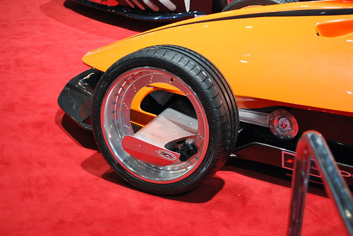
I understand the inside of the wheel itself being a big void probably contributes more drag than the spokes, but say you had streamlined spokes instead of the typical rectangular chunks, how much of a difference would that make? Would you be better off with a partial cover (a full cover missing a circle in the middle)?
|
The concept of a streamlined spoke is kinda oxymoronish if you think about them.
*In a calm situation,the spokes are shielded inside the wheel from the oncoming flow.
*They are churning within an environment of sequestered air.
*Their boundary layers and individual wakes travel in a circular train with the wheel.
*If their next to an open engine bay,we'd probably have transverse flow,moving through the turning spokes,creating a pulsation perturbation which destroys the flow.
*If in a crosswind,some of the spokes may remain shielded,while others are attacked by the free-stream entering the void.
*If the spokes were airfoil sections,they'd perhaps have a minimum windage drag in the context of their peculiar flow,but it would still be intermittent flow.
*You can't model this in CFD yet.
*It would cost perhaps a $100,000 to experiment with them in a tunnel.
*Low drag concepts use full wheelcovers (or full disc wheels) inside a full skirt,if not with an inner fender as with Ford's Probe-IV.
*As far as aesthetics and aero go,the closer you get to a full disc the better the drag situation,but then you lose the 'look.'
*If you were to cover partially,you'd cover the center and leave your opening out close to the rim.
__________________
Photobucket album: http://s1271.photobucket.com/albums/jj622/aerohead2/
|
|
|

|
|
The Following 3 Users Say Thank You to aerohead For This Useful Post:
|
|
 08-14-2014, 12:42 AM
|
#23 (permalink)
|
|
Master EcoModder
Join Date: Jan 2012
Location: United States
Posts: 1,756
Thanks: 104
Thanked 407 Times in 312 Posts
|
Quote:
Originally Posted by aerohead

The concept of a streamlined spoke is kinda oxymoronish if you think about them.
*In a calm situation,the spokes are shielded inside the wheel from the oncoming flow.
*They are churning within an environment of sequestered air.
*Their boundary layers and individual wakes travel in a circular train with the wheel.
*If their next to an open engine bay,we'd probably have transverse flow,moving through the turning spokes,creating a pulsation perturbation which destroys the flow.
*If in a crosswind,some of the spokes may remain shielded,while others are attacked by the free-stream entering the void.
*If the spokes were airfoil sections,they'd perhaps have a minimum windage drag in the context of their peculiar flow,but it would still be intermittent flow.
*You can't model this in CFD yet.
*It would cost perhaps a $100,000 to experiment with them in a tunnel.
*Low drag concepts use full wheelcovers (or full disc wheels) inside a full skirt,if not with an inner fender as with Ford's Probe-IV.
*As far as aesthetics and aero go,the closer you get to a full disc the better the drag situation,but then you lose the 'look.'
*If you were to cover partially,you'd cover the center and leave your opening out close to the rim.
|
Thanks for the insight.
Why would you want to cover the center with a partial cover though? I can't wrap my head around this...Aren't the spokes moving faster at the edge of the rim?
On the same note, I noticed that some cars have the wheels flush to the side of the car, but others (such as my car, and other Toyotas from the same time period) have the fender poking out more at the top of the wheel and receding towards the bottom, would this possibly "isolate" the air being churned by the wheels better? |
|
|

|
 08-14-2014, 03:17 AM
|
#24 (permalink)
|
|
Master EcoWalker
Join Date: Dec 2012
Location: Nieuwegein, the Netherlands
Posts: 4,005
Thanks: 1,716
Thanked 2,252 Times in 1,458 Posts
|
Quote:
Originally Posted by serialk11r

Why would you want to cover the center with a partial cover though? I can't wrap my head around this...Aren't the spokes moving faster at the edge of the rim?
|
A full cover on a rim with holes will trap rain, dirt etc.
The holes in my steel rims were small, but even in 2 weeks time my full covers trapped a lot of dirt.
If you don't seal the gaps on the rim you better have the hub cap open at the edge.
Aerodynamically it is almost impossible to make the transition from tire/rim edge to hub cap completely flush. (*)
If you are to have a gap in your wheel cover you better have it where the air flow is disturbed anyway - close to the rim edge.
(*) The very same minute that I posted this, Niky showed how it can be done:
 http://ecomodder.com/forum/showthrea...tml#post440055
Thanks Niky 
__________________
2011 Honda Insight + HID, LEDs, tiny PV panel, extra brake pad return springs, neutral wheel alignment, 44/42 PSI (air), PHEV light (inop), tightened wheel nut.
  lifetime FE over 0.2 Gigameter or 0.13 Megamile.

For confirmation go to people just like you.
For education go to people unlike yourself.
Last edited by RedDevil; 08-14-2014 at 03:39 AM..
|
|
|

|
|
The Following User Says Thank You to RedDevil For This Useful Post:
|
|
 08-14-2014, 04:17 AM
|
#25 (permalink)
|
|
Master EcoModder
Join Date: Aug 2010
Location: Philippines
Posts: 2,173
Thanks: 1,739
Thanked 589 Times in 401 Posts
|
Not so fast, Red. That's a rubber cap! In fact, had one fly off. So much pressure built up under the cap that the tape alone couldn't hold it... the spokes were simply too thin.
Good thing it wasn't plywood! 
I guess, however, you can still use duct tape to fill the edges for a smooth transition to the tire with a pizza pan. |
|
|

|
 08-14-2014, 07:18 AM
|
#26 (permalink)
|
|
Master EcoWalker
Join Date: Dec 2012
Location: Nieuwegein, the Netherlands
Posts: 4,005
Thanks: 1,716
Thanked 2,252 Times in 1,458 Posts
|
One of the underbody panels on my Insight has a strange dimple. It does not look aerodynamic at all.
From 2012 onwards Honda mounts a flush dimpleless panel...
I covered the dimple with some thick plastic foil and glued and taped it with duct tape about a year ago.
The tape on the front has withered and I had to tear the remnants off.
Duct tape won't last forever.
__________________
2011 Honda Insight + HID, LEDs, tiny PV panel, extra brake pad return springs, neutral wheel alignment, 44/42 PSI (air), PHEV light (inop), tightened wheel nut.
  lifetime FE over 0.2 Gigameter or 0.13 Megamile.

For confirmation go to people just like you.
For education go to people unlike yourself.
|
|
|

|
 08-14-2014, 05:36 PM
|
#27 (permalink)
|
|
Master EcoModder
Join Date: Jan 2008
Location: Sanger,Texas,U.S.A.
Posts: 16,548
Thanks: 24,522
Thanked 7,442 Times in 4,822 Posts
|
why the center
Quote:
Originally Posted by serialk11r

Thanks for the insight.
Why would you want to cover the center with a partial cover though? I can't wrap my head around this...Aren't the spokes moving faster at the edge of the rim?
On the same note, I noticed that some cars have the wheels flush to the side of the car, but others (such as my car, and other Toyotas from the same time period) have the fender poking out more at the top of the wheel and receding towards the bottom, would this possibly "isolate" the air being churned by the wheels better?
|
The inner face of the rim provides a duct 'wall' which is in the area unobstructed by the rotor and hub.Tranverse flow can move as freely as possible,through the spokes and out.
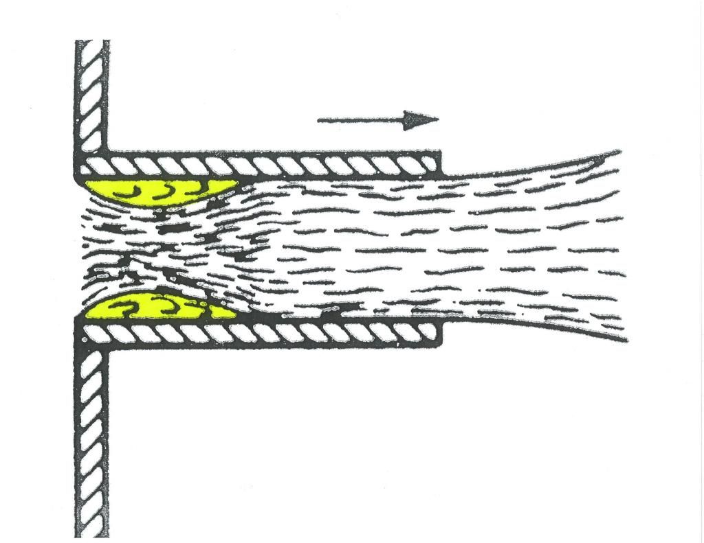
If you sealed this area and opened the center,you'd be asking the air to make a right-angled turn past a Cd 1.11 flat plate(rotor) within the wheel and flow towards and through an equally 'draggy'
vena contracta.

Here is a Borda tube with the vena contracta (in yellow).You can see how the flow is choked off even though it's an 'open' hole.
It's a torture chamber as far as airflow goes.
If you keep the flow near the rim you have more interior space to provide some radii inside the cover to kill the vena contracta with.Think of an inside-out velocity stack/outside curve of a donut inside the cover.
This internal drag far outweighs any penalty due to the spokes.
__________________
Photobucket album: http://s1271.photobucket.com/albums/jj622/aerohead2/
|
|
|

|
|
The Following 3 Users Say Thank You to aerohead For This Useful Post:
|
|
 08-14-2014, 09:06 PM
|
#28 (permalink)
|
|
Master EcoModder
Join Date: Aug 2012
Location: northwest of normal
Posts: 29,460
Thanks: 8,384
Thanked 9,142 Times in 7,548 Posts
|
I learned a new word[s].
 |
|
|

|
|
The Following User Says Thank You to freebeard For This Useful Post:
|
|
 08-14-2014, 09:52 PM
|
#29 (permalink)
|
|
Master EcoModder
Join Date: Aug 2010
Location: Philippines
Posts: 2,173
Thanks: 1,739
Thanked 589 Times in 401 Posts
|
Quote:
Originally Posted by RedDevil

Duct tape won't last forever.
|
Mine didn't even last a day.
Granted, I should have wiped down the wheels with some really good cleaner, but there just isn't enough purchase on porous rubber for the duct tape (it's okay where I used it on the airdams, because it sticks to automotive finishes quite well.
Too well, in fact.
One thought... you can actually vulcanize thin sheets of rubber to the sidewall. Perhaps make a doughnut shape out of rubber, then attach it to the sidewall, leaving a hole in the center for a thin, flush-mounted aero cap.
Hmmm.... |
|
|

|
 08-15-2014, 04:47 PM
|
#30 (permalink)
|
|
Master EcoModder
Join Date: Aug 2012
Location: northwest of normal
Posts: 29,460
Thanks: 8,384
Thanked 9,142 Times in 7,548 Posts
|
vena contracta
I spent an entertaining but fruitless hour trying to find a jpeg I saved years ago. It was an early example of using 3D graphics to show anatomical details and was a chart of branches in arterial/veinal structures. As a general rule, sidebranches were at 60°, not 90° and the main flow path was non-linear (i.e., hydro-formed).
The closest I have been able to find is this:
 Possibility of Atherosclerosis in an Arterial Bifurcation Model
This is a model simplified for computational purposes; reality more closely follows Victor Shauberger. 3D printed induction/exhaust will rule.
|
|
|

|
|