Hello Everyone,
I have put together a design for a new motor control board based on the Revolt design. I will be calling this board the Uprising to keep confusion to a minimum.
I hope to direct traffic about the Uprising board to this thread as to not clutter Paul's already MASSIVE thread!
Thank You.
-Adam
V. 2.0.0
 Untitled
 by
AdamBrunette, on Flickr
23 Pin Weatherproof Automotive Connector: One of the biggest things I wanted to include was an easy way to disconnect the controller. I have found an affordable 23 pin weatherproof connector meant for automotive applications.
5 Universal Inputs: Each one of these inputs is capable of accepting a signal from 3.3 to 15v without damage. This means you can feed 5v TTL signals and automotive 12V signals into the controller. Each input is independent of the other so they can be used in any combination. One of these inputs has a special function of accepting a tach input signal.
4 Universal Outputs: Each of these outputs is supplying 12V from the controller, Common to the vehicles 12v system. This means you can easily run indicators that are tied to ground. One of these outputs is wired special for tach output as well.
Ethernet Communication: I have included ethernet communication on the board for easier configuration. Software will provide a web interface that will be accessible from anything device with a web browser (iPhone, Android, ect.)
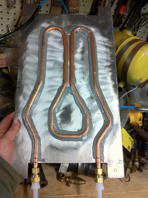
Built in Pre-Charge: This is done with solid state switching inside the logic board. Just 1 lead to outside the controller, on the live side of the contactor is all thats required.
Bus Voltage Monitoring: The controller measures the voltage inside the controller at the cap. This will be used for pre-charge and for motor and battery voltage limiting.
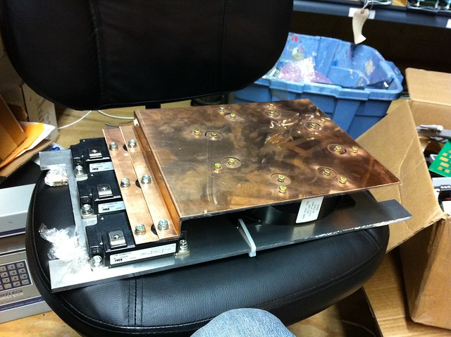
Universal Driver Output: The output section of the controller took alot of thought. I wanted something flexible, powerful and unlimited. What I came up with I think will fit the bill. The board is capable of driving mosfets directly, indirectly, or driving IGBT driving modules. I think thats everything!

Directly, the controller can be connected to 10 or so fets through some simple breakout and everything will work good. Indirectly, There is also the ability to driver remote mosfet drivers at high voltage to resist noise and have alot of drivers. And , IGBT's. The driver chip can be changed out to a non-inverting driver to drive VLA-500 modules, and jumpers reset to provide 5V high current output.
Throttle Options
Single 2 Wire Potentiometer
Dual 2 Wire Potentiometer (Inverted or Normal)
Single 3 Wire Potentiometer
Dual 3 Wire Potentiometer (Inverted or Normal)
Single Hall Effect Sensor
Dual Hall Effect Sensor (Inverted or Normal)
Other Features: I decided to keep serial on the controller because I had room and if people want to poll or tell the controller to do things over simple serial they would still be able to. Throttle section is the same, as well as contactor control, temp sensor, current measurement and under-voltage circuitry.
This controller uses a very different AVR though. I have moved to a Atmega 644p. This provides 32 IO, and I used all but 4!
Now, Some of you will be disappointed in my next decision, but believe me, it was not made lightly.
I have designed the board in all surface mount components, except for optos and the DC-DC.
This brings me to my next statement. After prototyping is complete, I will be offering pre built logic boards. These will be professionally assembled on assembly machines. Once a few boards are made and purchased, I hope to always keep a few controllers on hand ready for shipment. They will be tested and loaded with the latest firmware.
Schematic:
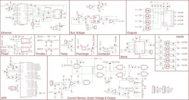 Uprising Rev2 Sch
 by
AdamBrunette, on Flickr
Layout:
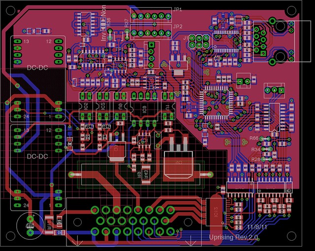 Uprising Rev2
 by
AdamBrunette, on Flickr
Current Revision: 2.0.4
11/23/11
I have finished populating 90% of the prototype of version 2.0.0 . While doing this, I made a video showing the process of hand building an SMD board. Enjoy.


 Today
Today


 ...
...


 . ....
 ...
...