 03-15-2016, 02:23 PM
|
#11 (permalink)
|
|
Master EcoModder
Join Date: Jan 2008
Location: Sanger,Texas,U.S.A.
Posts: 16,514
Thanks: 24,517
Thanked 7,436 Times in 4,817 Posts
|
what does plan taper mean to us?
*we're trying to reduce flow separation in the aft-body or eliminate it.
*streamline body-based bodies cannot trigger flow separation.
*the reason is that the gradual pressure rise along top and sides is so gradual and progressive as to not jeopardize the turbulent boundary layer's ability to tolerate it.
*it's an area rule/sectional density issue.
*since the published data infers that the profile of a 2.5:1 streamline body would be essentially ideal for an automotive body,then it's aft-body contour suggests a benchmark,or 'template' for a low-drag tail.
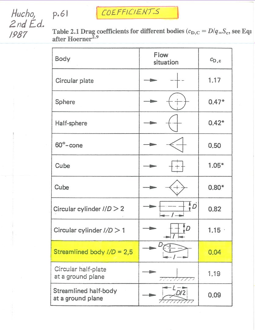
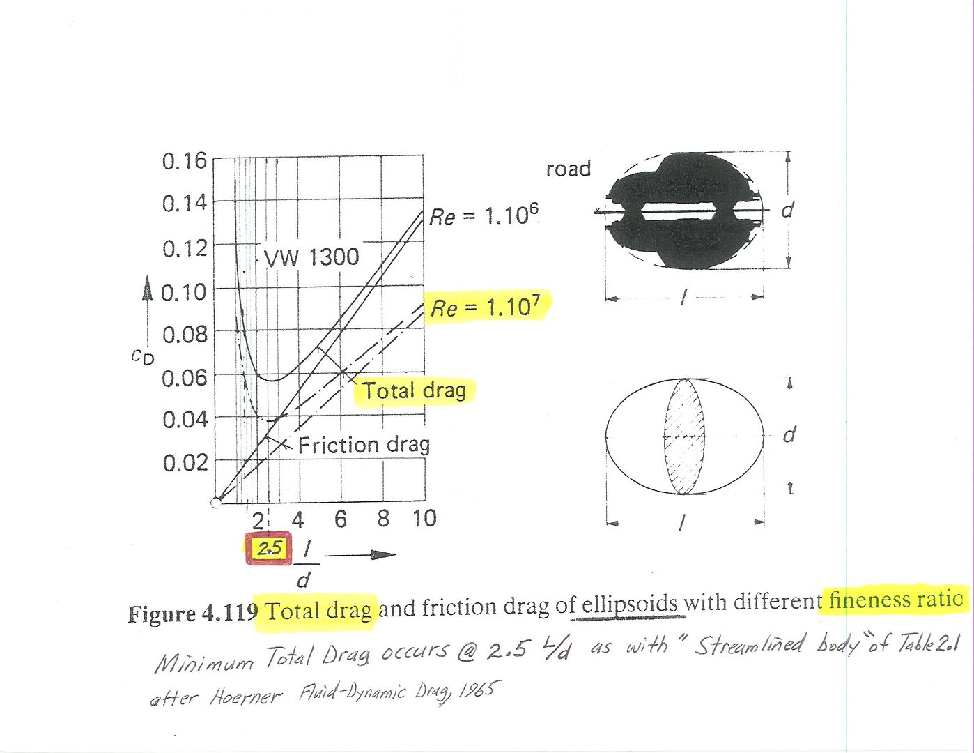
*W.A.Mairs' boat tail is the easiest to construct and is very similar to the 2.5:1 profile,so we might use it's cross-sectional architecture as a safe profile.
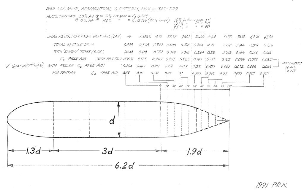
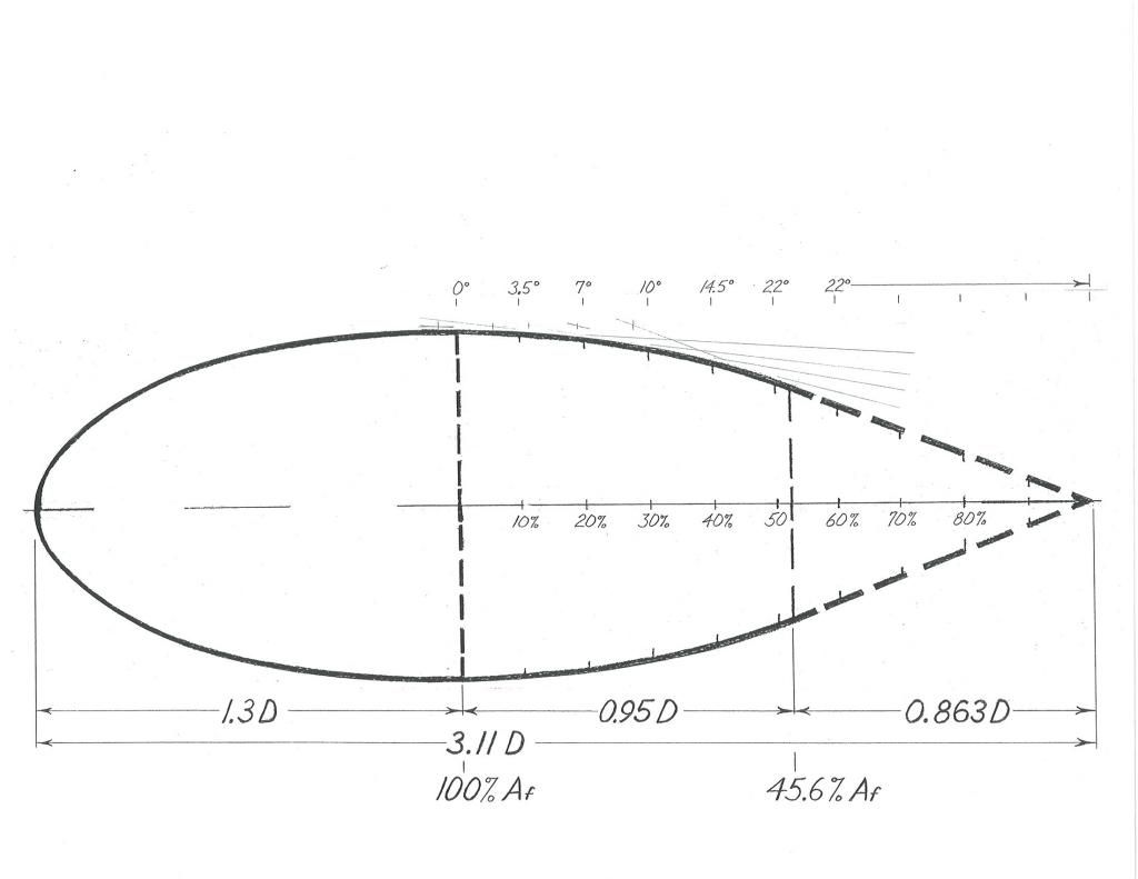
*no element of the aft-bodies cross-sectional area would vary any more than that of Mair's tail.It could be square/round/'squircle' (freebeard),etc.,or morph from one to the other as long as it's overall cross-section doesn't violate the percentage difference from one position to another.
*Morelli appears to encourage oval or circular transom,due to his 'fluid tail' ring-vortex,phantom tail pheneomena.
Here,some members have done this with their boat tail extensions
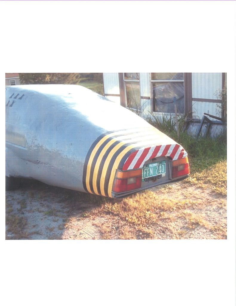
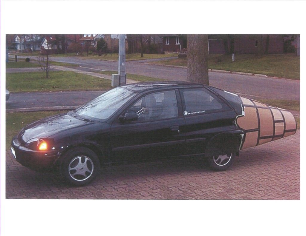
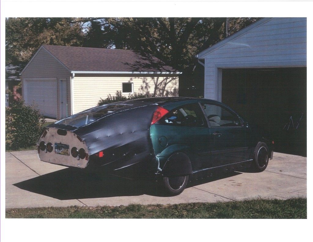
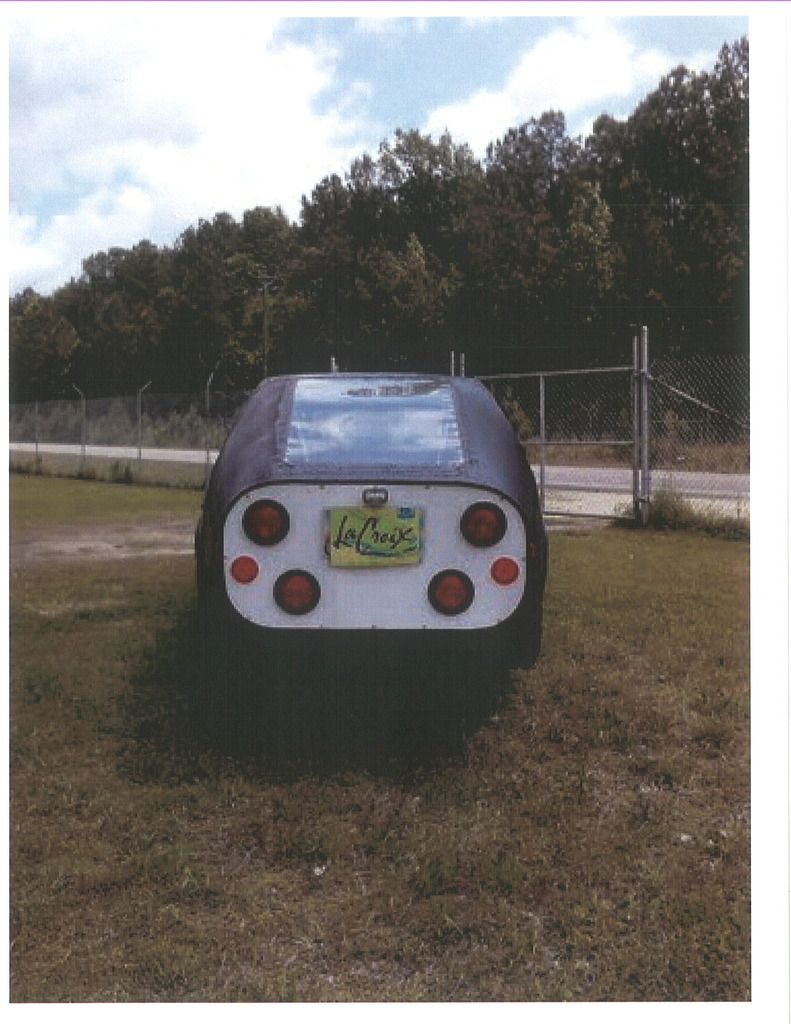
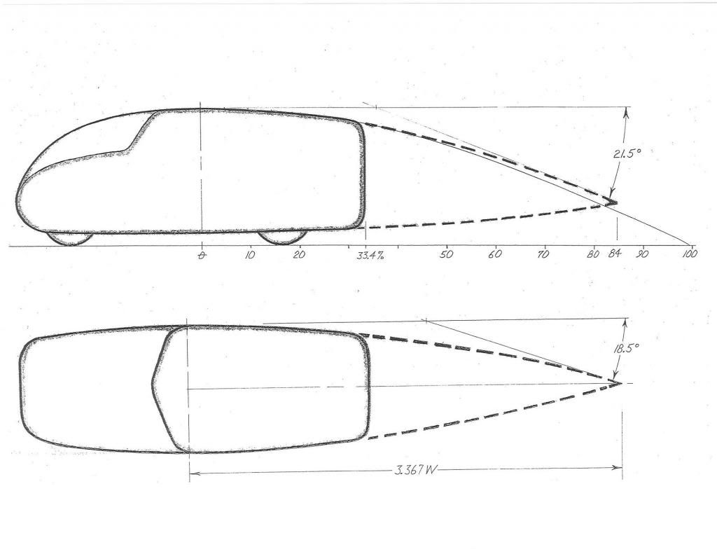
*the plan-view taper defines the limits we can expect when designing the side body taper of our mods.
*you can go 'slower' with the curvature and pay a little skin friction penalty,but you should never go 'faster' than the curve unless you've got really good CFD or wind tunnel 'proof' that it will work.Hucho warns of velocity/pressure 'kinks' along the air's pathway that can trigger vorticity or separation,exactly what we're trying to eliminate.
*The longer the body the better.Only you can decide your 'limits.'
Kamm's full body car
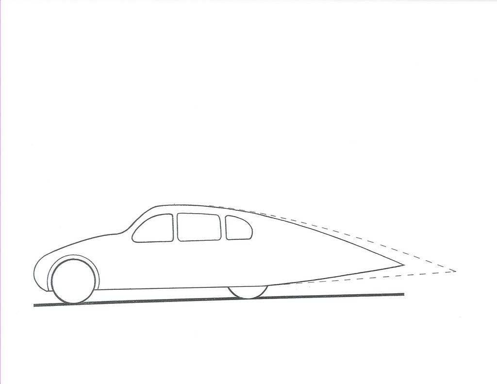
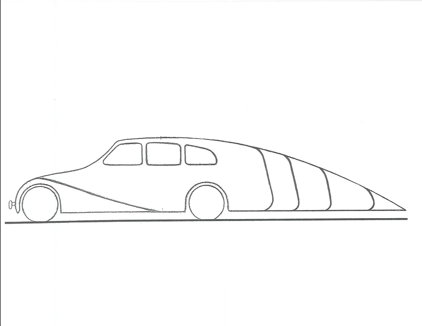
Kamm's recommendation for an extensible highway tail
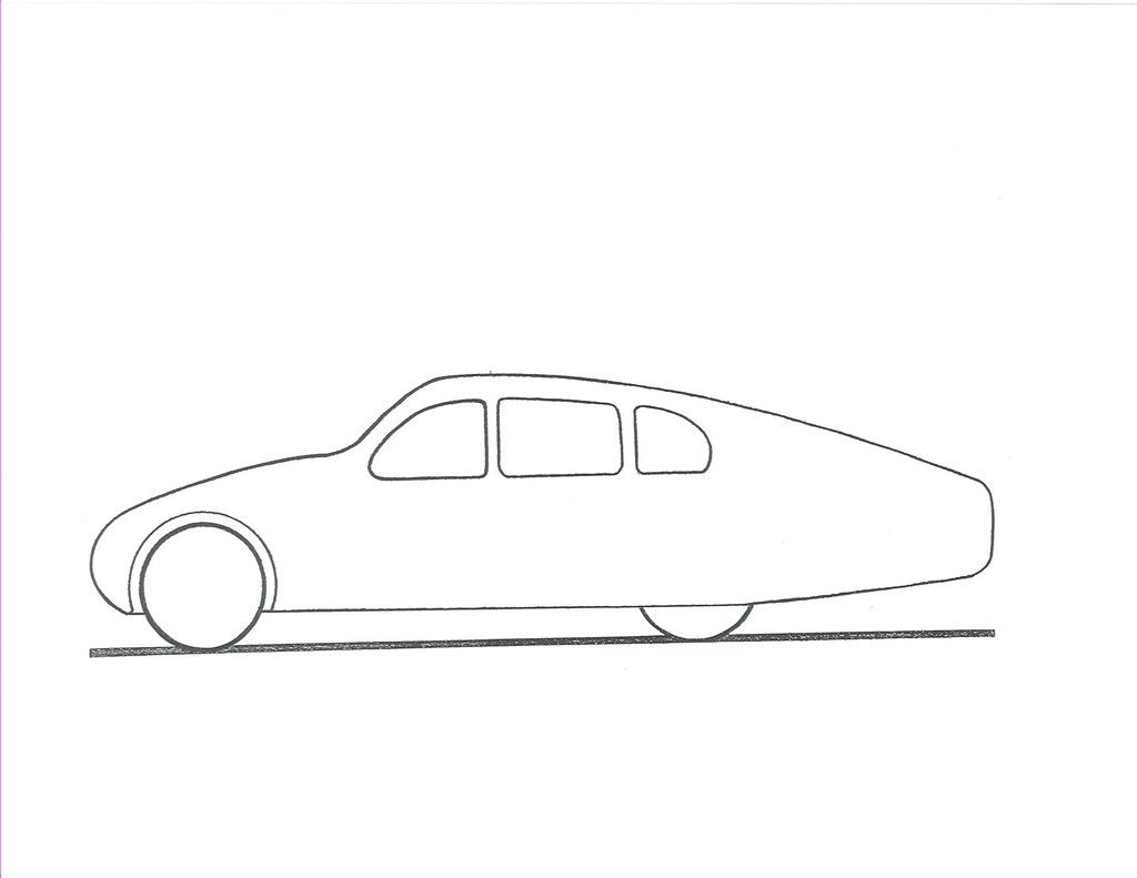
Kamm's recommendation for the 'stowed-tail' urban environment
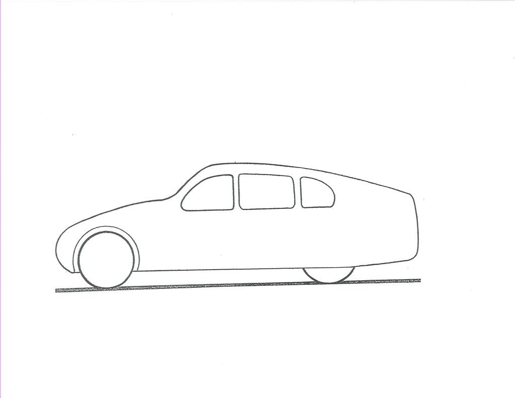
Kamm's plan-view
__________________
Photobucket album: http://s1271.photobucket.com/albums/jj622/aerohead2/
|
|
|

|
|
The Following User Says Thank You to aerohead For This Useful Post:
|
|
 Today Today
|
|
|
|
 Other popular topics in this forum...
|
|
|
|
 03-19-2016, 04:21 PM
|
#12 (permalink)
|
|
Master EcoModder
Join Date: Jan 2008
Location: Sanger,Texas,U.S.A.
Posts: 16,514
Thanks: 24,517
Thanked 7,436 Times in 4,817 Posts
|
bounds of discussion
Quote:
Originally Posted by freebeard

I'm waiting to learn the bounds of discussion. Everyone else just Thanked you and moved on.
Old Tele man -- your joke lives on in email notifications.
|
*At the Aerodynamic Streamlining Template Part-C thread there were some questions about how the aft-body plan profile would be addressed for streamlining,when considering the AST.
*I felt that this topic deserved it's own dedicated thread so it didn't get buried at the other thread,which is running to many,many pages now.
*I wanted to plant the seed of the discussion with images of how this task has been approached by others,some of which include drag coefficients which elude to how successful a particular profile turned out.This will save me millions of words.
*I'll attempt an independent 'square-to-round' thread as well in the near future after I'm more confident about some of the geometry/area data.
-------------------------------------------------------------------------
*The major theme is that whether we stick with the original frontal/rearward vertical elevation profile of our candidate vehicle,or morph it from,say,square-ish,to more 'round-ish',we should not allow the cross-sectional area to ever vary any more than that of the streamline body of revolution of near fineness ratio 2.5:1,to protect the velocity/static pressure profile.(which protects the boundary layer from separating)
--------------------------------------------------------------------------
*keeping track of the areas may entail breaking each cross-section into elements of squares,rectangles,circles,and elliptical areas.Which should be easier than ever with online calculators.
-------------------------------------------------------------------------
*Most production vehicles have bodies which attain roof convergence before side body convergence and when viewed from above will have to respect the fact that the plan-view streamlining will have to lag behind that of the roof/greenhouse.
__________________
Photobucket album: http://s1271.photobucket.com/albums/jj622/aerohead2/
|
|
|

|
 03-21-2016, 06:41 AM
|
#13 (permalink)
|
|
Master EcoModder
Join Date: May 2011
Location: Syracuse, NY USA
Posts: 2,935
Thanks: 326
Thanked 1,315 Times in 968 Posts
|
This shows clearly that when streamlinig a truncated shape that half the improvements can be lost at the back.
.
.

.
.
. |
|
|

|
|
The Following 2 Users Say Thank You to sendler For This Useful Post:
|
|
 03-21-2016, 11:56 AM
|
#14 (permalink)
|
|
Master EcoModder
Join Date: Aug 2012
Location: northwest of normal
Posts: 29,366
Thanks: 8,354
Thanked 9,118 Times in 7,528 Posts
|
Quote:
|
*I'll attempt an independent 'square-to-round' thread as well in the near future after I'm more confident about some of the geometry/area data.
|
The transition from square to round is defined by the superellipse equation with 1< n<2. Just run the subset (not quite square to not round) solving for area backward for each % reduction in area at subsequent longitudinal stations.
Quote:
The area inside the superellipse can be expressed in terms of the gamma function, Γ(x), as:
\mathrm{Area} = 4 a b \frac{\left(\Gamma \left(1+\tfrac{1}{n}\right)\right)^2}{\Gamma \left(1+\tfrac{2}{n}\right)} .
|
|
|
|

|
|
The Following User Says Thank You to freebeard For This Useful Post:
|
|
 03-21-2016, 04:35 PM
|
#15 (permalink)
|
|
EcoModding Lurker
Join Date: Mar 2015
Location: -
Posts: 30
Thanks: 3
Thanked 12 Times in 11 Posts
|
Quote:
Originally Posted by sendler

This shows clearly that when streamlinig a truncated shape that half the improvements can be lost at the back.
.
.

.
.
. |
I keep looking at it and can't seem to read it otherwise: J-form is better than K-form.
This contradicts what I used to know. Can anyone explain what's up?
|
|
|

|
|
The Following User Says Thank You to gafhj For This Useful Post:
|
|
 03-21-2016, 04:58 PM
|
#16 (permalink)
|
|
Master EcoModder
Join Date: Aug 2012
Location: northwest of normal
Posts: 29,366
Thanks: 8,354
Thanked 9,118 Times in 7,528 Posts
|
"I try to think but nothing happens"
Maybe it's that the chart compares fineness ratio and truncation, in dimensionless numbers? Apple and oranges?
|
|
|

|
 03-21-2016, 06:08 PM
|
#17 (permalink)
|
|
Master EcoModder
Join Date: May 2011
Location: Syracuse, NY USA
Posts: 2,935
Thanks: 326
Thanked 1,315 Times in 968 Posts
|
Quote:
Originally Posted by gafhj

J-form is better than K-form.
|
If the chart is accurate it is showing that for any given total length, the J form has nearly half the drag of the K form until you get out to the last 10-20% where the Kamm truncation is not so much of a loss. |
|
|

|
 03-21-2016, 10:55 PM
|
#18 (permalink)
|
|
Master EcoModder
Join Date: Aug 2012
Location: northwest of normal
Posts: 29,366
Thanks: 8,354
Thanked 9,118 Times in 7,528 Posts
|
The overall lengths are not equal, by about 5%. The diameters are. The shorter lengths are disparate.
Kt=60 has no analog in J and the J curve is incommensurate with the horizontal scaling.
Possibly you could say that, in general, the area between the curves represents the benefit from wake stuffing.
|
|
|

|
|
The Following User Says Thank You to freebeard For This Useful Post:
|
|
 03-22-2016, 05:14 PM
|
#19 (permalink)
|
|
Master EcoModder
Join Date: Jan 2008
Location: Sanger,Texas,U.S.A.
Posts: 16,514
Thanks: 24,517
Thanked 7,436 Times in 4,817 Posts
|
truncated
Quote:
Originally Posted by sendler

This shows clearly that when streamlinig a truncated shape that half the improvements can be lost at the back.
.
.

.
.
. |
Bear in mind that these structures are 2D airfoil sections,like the fuselage of AeroVironment's human-powered airplane.
For 3D auto bodies,Kamm's bread chop truncations would have an advantage except at fairly long lengths.
__________________
Photobucket album: http://s1271.photobucket.com/albums/jj622/aerohead2/
|
|
|

|
 03-22-2016, 05:18 PM
|
#20 (permalink)
|
|
Master EcoModder
Join Date: Jan 2008
Location: Sanger,Texas,U.S.A.
Posts: 16,514
Thanks: 24,517
Thanked 7,436 Times in 4,817 Posts
|
J-form better
Quote:
Originally Posted by gafhj

I keep looking at it and can't seem to read it otherwise: J-form is better than K-form.
This contradicts what I used to know. Can anyone explain what's up?
|
These are 2D wing section models.
For 3D auto bodies the Kamm truncation would have the advantage,unless at rather long lengths,where it's a 'wash' between the two types.
__________________
Photobucket album: http://s1271.photobucket.com/albums/jj622/aerohead2/
|
|
|

|
|