 03-10-2021, 08:33 PM
|
#1 (permalink)
|
|
Master EcoModder
Join Date: Aug 2012
Location: northwest of normal
Posts: 28,917
Thanks: 8,202
Thanked 8,983 Times in 7,420 Posts
|
Duct Duct Go
It's been a while since I had an idea that is unquestionable excellent (at least IMHO).
I'll list my sources later, but I've been frustrating myself with the 3D software so I went back to what works, pencil drawing, 5 Megapixel camera, slam the brightness and contrast and reduce in the GIMP. Took about 1/2 hour.
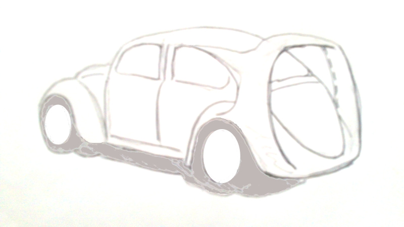
Pix on request, but off the top - the Austin Windmobile
- Jetopera
- Dyson Bladeless fan
- my earlier Coanda boat tail
- VW GTI W-12 650
Essentially, this: The exhaust on the flat four consists of four J-tubes joined with a 90 degree elbow. So two upward facing exhausts close behind the rear wheels. These are centered in rerouted cooling air ducts that flow upward on either side of the rear window.
<stainless steel|aluminum>
The rear wing is an aluminum tube bent to shape and then slit end to end somewhere on the inner side TBD. Small wedges are inserted and twisted to part the two edges by a fraction of an inch and then spot welded.
This become a spar for an airfoil. While the tube is perpendicular the leading and trailing edge will be more like Colani or the Porsche 959. I propose a 1/18th scale model next because I have one I don't like the color of.
Good Lord willin' and the creek don't rise, I might have more later.
__________________
.
.Without freedom of speech we wouldn't know who all the idiots are. -- anonymous poster
|
|
|

|
|
The Following 4 Users Say Thank You to freebeard For This Useful Post:
|
|
 Today Today
|
|
|
|
 Other popular topics in this forum...
|
|
|
|
|
03-11-2021, 08:31 AM
|
#2 (permalink)
|
|
Master EcoModder
Join Date: Nov 2020
Location: The Pas, Manitoba
Posts: 319
Thanks: 427
Thanked 147 Times in 113 Posts
|
I really like this look. You must really like that Golf, hey? 
So how does this help with FE? Does it correct some of the airflow at the rear? |
|
|
|
|
03-11-2021, 11:01 AM
|
#3 (permalink)
|
|
Somewhat crazed
Join Date: Sep 2013
Location: 1826 miles WSW of Normal
Posts: 4,479
Thanks: 562
Thanked 1,221 Times in 1,078 Posts
|
What are your plans for the cooling airflow? I also assume your spare stroker engine because I am unsure which flat 4 motor.
|
|
|
|
|
03-11-2021, 02:35 PM
|
#4 (permalink)
|
|
Master EcoModder
Join Date: Aug 2012
Location: northwest of normal
Posts: 28,917
Thanks: 8,202
Thanked 8,983 Times in 7,420 Posts
|
Quote:
|
Originally Posted by JacobLeSann
You must really like that Golf, hey? |
Can't deny it's one of my favorites, but this is a first approximation. I could substitute a Jim Dandy roof rack.
 https://i.ebayimg.com/images/i/16263...-1/s-l1000.jpg
Piotrsko -- Stock fan and shroud, except instead of dumping air to the rear, it goes into a vertical chimney behind each rear tire. It is entrained by the exhaust and the only exit is from the approx. 8ftx2" plenum who's only exit is a slot that run around the inside of the arc.
Where I need help is determining the relation of the volume of air available vs the cross section of the duct. I think this determines the width of the slot.
I think the stock fan wouldn't be overburdened because the exhaust is 'pulling' on the cooling air. But in my original Coanda boat tail, I specified only cooling air because exhaust is corrosive and nasty.
I have the motor in my Superbeetle but I'm not cutting that up. I'm also hoarding a 36hp case but it's incomplete.
__________________
.
.Without freedom of speech we wouldn't know who all the idiots are. -- anonymous poster
|
|
|
|
|
03-11-2021, 04:40 PM
|
#5 (permalink)
|
|
Master EcoModder
Join Date: Nov 2012
Location: San Diego, California
Posts: 982
Thanks: 271
Thanked 385 Times in 259 Posts
|
I really like this discussion and concept.
I remember reading about how the designers of the Japanese Zero fighter fooled with the exhaust stacks to eek out a few more knots of speed at full throttle.
Also, didn't the Mosquito Fighter Bomber of that same time period use radiator heated air to create forward thrust?
This bears investigation if we are to use ICEs .
|
|
|
|
|
The Following 2 Users Say Thank You to RustyLugNut For This Useful Post:
|
|
|
03-12-2021, 11:06 AM
|
#7 (permalink)
|
|
Somewhat crazed
Join Date: Sep 2013
Location: 1826 miles WSW of Normal
Posts: 4,479
Thanks: 562
Thanked 1,221 Times in 1,078 Posts
|
I would think if you know rpm you can estimate fan output based on size of opening, but I think that an approximation of that size would suffice since you ARE reducing it with the exhaust flow. Depends on how high the static pressure of the duct needs to be, but that is so far above my pay grade.......
Can't see any use for the 36 case except for old timey full restos which are gonna be really rare and involve cyphering the case serial number (I think they had one) dual port conversion are so common and cheap anymore.......
|
|
|
|
|
03-12-2021, 11:41 AM
|
#8 (permalink)
|
|
Master EcoModder
Join Date: Jan 2008
Location: Sanger,Texas,U.S.A.
Posts: 16,381
Thanks: 24,467
Thanked 7,406 Times in 4,798 Posts
|
forwards thrust
Quote:
Originally Posted by RustyLugNut

I remember reading about how the designers of the Japanese Zero fighter fooled with the exhaust stacks to eek out a few more knots of speed at full throttle.
Also, didn't the Mosquito Fighter Bomber of that same time period use radiator heated air to create forward thrust?
This bears investigation if we are to use ICEs .
|
I believe that it was the P-51 Mustang which has been reported on with respect to heated, air, coming off the oil cooler producing some thrust.
This couldn't work on a subsonic automobile, as it requires compressibility effects of transonic, or supersonic flow to be present.
The exhaust thrust, I believe, was associated with the Messerschmitt Bf 109 fighter.
__________________
Photobucket album: http://s1271.photobucket.com/albums/jj622/aerohead2/
Last edited by aerohead; 03-17-2021 at 11:27 AM..
Reason: correction
|
|
|
|
|
03-12-2021, 02:45 PM
|
#9 (permalink)
|
|
Master EcoModder
Join Date: Aug 2012
Location: northwest of normal
Posts: 28,917
Thanks: 8,202
Thanked 8,983 Times in 7,420 Posts
|
I mis-spoke at #6. The FW-190 and similar had engine-driven fans on radial engines, The Meredith effect was passive.
Quote:
|
I believe that it was the P-51 Lightning
|
 P-51 Mustang, P-38 Lightning.
__________________
.
.Without freedom of speech we wouldn't know who all the idiots are. -- anonymous poster
|
|
|
|
|
The Following User Says Thank You to freebeard For This Useful Post:
|
|
|
03-12-2021, 07:00 PM
|
#10 (permalink)
|
|
Master EcoModder
Join Date: Aug 2012
Location: northwest of normal
Posts: 28,917
Thanks: 8,202
Thanked 8,983 Times in 7,420 Posts
|
aerohead -- Thanks for giving this your attention. I'm looking at a die-cast scale model and it looks like a [no more than] 4" inverted U-shape leading edge for an airfoil.
Given, say, 250cfs of flow (25 times 10x) through the duct what should it's area be? I'd address the slot opening later.
I'm comparing a minimalist vertical hoop with something more like the Bird of Prey:
 https://nationalinterest.org/sites/d...s/boeing_0.jpg https://nationalinterest.org/sites/d...s/boeing_0.jpg
I think it could have an angled intake throat if the plenum is fed from the quarter-points instead of the ends.
__________________
.
.Without freedom of speech we wouldn't know who all the idiots are. -- anonymous poster
|
|
|
|
|
The Following User Says Thank You to freebeard For This Useful Post:
|
|
|


