 07-25-2015, 12:20 PM
|
#11 (permalink)
|
|
Master EcoModder
Join Date: Jan 2008
Location: Sanger,Texas,U.S.A.
Posts: 16,539
Thanks: 24,520
Thanked 7,439 Times in 4,819 Posts
|
trout
Quote:
Originally Posted by freebeard

The engineering is rudimentary. Maybe he was dumb-ing it down for his times. His inspiration was realizing trout can keep station in a moving stream of water by gulping water through their gills. They flick their tail when they want to go somewhere.
|
A trout would be a nice form to mimic.Sir George Cayley used a lake trout for his aeronautical studies.NACA developed an airfoil section which is virtually identical to Cayley's lake trout.
The 455-mph Speed Demon body was inspired by a Coho Salmon.Good technology! 
__________________
Photobucket album: http://s1271.photobucket.com/albums/jj622/aerohead2/
|
|
|

|
|
The Following User Says Thank You to aerohead For This Useful Post:
|
|
 Today Today
|
|
|
|
 Other popular topics in this forum...
|
|
|
|
 07-25-2015, 03:42 PM
|
#12 (permalink)
|
|
EcoModding Lurker
Join Date: Mar 2015
Location: California
Posts: 92
Thanks: 10
Thanked 19 Times in 17 Posts
|
That's sort of what my idea entails:

The cross-ducting is so that when the bike's hit with a side-wind, it'll channel some of that air to the opposite side of the bike to counteract the side-wind loading and hence lessen the effect of the side-wind.
During straight-line riding, not much air will be scooped via the cross-over ducts, since the amount of duct exposed to straight-on air flow is small. What air is scooped during straight-line riding will be equal on both sides of the bike, thus the forces will be equal.
The blackish objects in the cross-over ducts are the two radiators. They'll cool the engine, and the heating of the air will serve to provide more counter-force to counteract side-winds.
The venturi scoop at the front provides cooling air to the engine compartment. Its warm air and the engine exhaust are discharged at the rear of the Kamm tail to "fill the void" and lessen rearward drag.
The venturi scoop at the front also works to remove that "stalled" air at the direct front of the bike, lessening the pressure wave the bike has to push through.
Last edited by Cycle; 07-25-2015 at 03:50 PM..
|
|
|

|
|
The Following User Says Thank You to Cycle For This Useful Post:
|
|
 07-25-2015, 04:19 PM
|
#13 (permalink)
|
|
Master EcoModder
Join Date: Jan 2008
Location: Sanger,Texas,U.S.A.
Posts: 16,539
Thanks: 24,520
Thanked 7,439 Times in 4,819 Posts
|
idea
I'm gonna throw out some thoughts
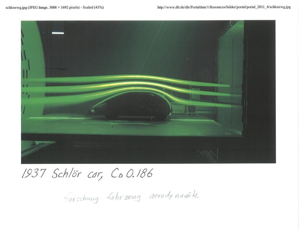
*The forward stagnation point is not a drag producer.Long before the air makes it to the body,it's already displacing to streamline itself,as demonstrated by Ludwig Prandtl almost a century ago.
Here you can see it happening to the 1937 Schl'o'r pillbug car.
*The side area of the bike is so large in comparison to the pressure bleeding ducts,that there might not be enough porosity in the body to mitigate the effects of a strong crosswind or gusts.
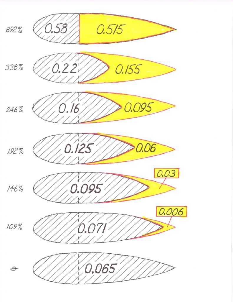
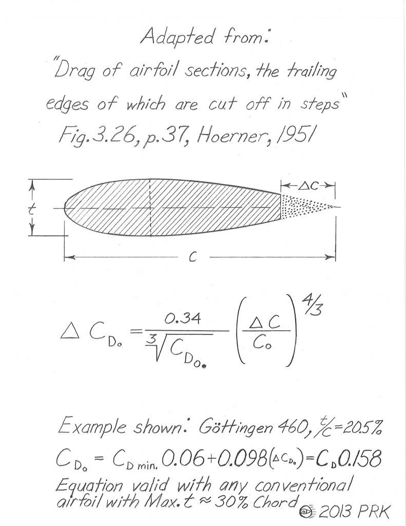
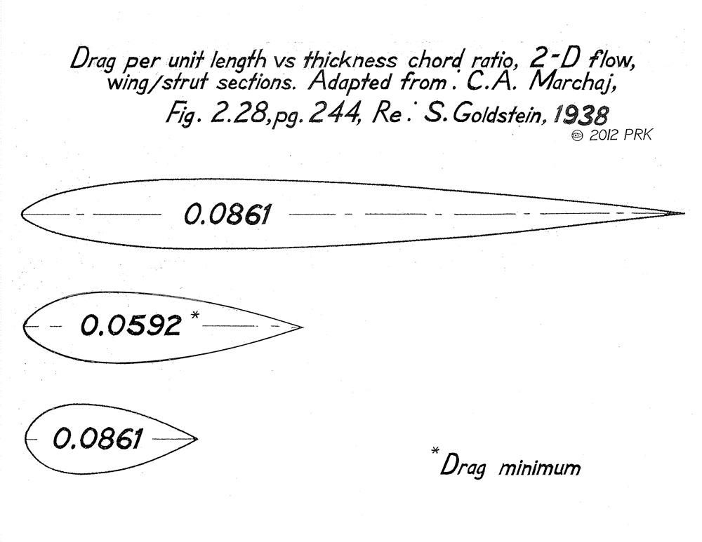
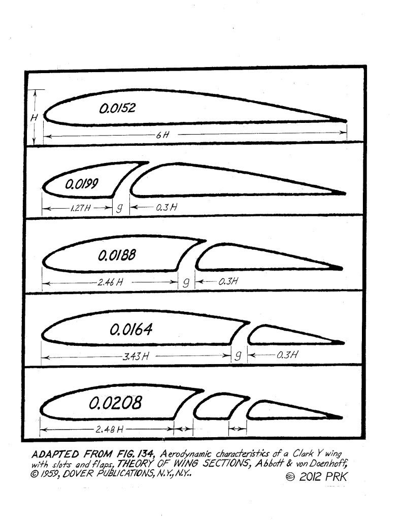
*Since you're relying on a vertical airfoil so to speak,they suffer tremendous drag when truncated like a Kamm back.It's better to have the trailing edges come together as a point,even if the curve is 'fast.'
__________________
Photobucket album: http://s1271.photobucket.com/albums/jj622/aerohead2/
|
|
|

|
|
The Following 2 Users Say Thank You to aerohead For This Useful Post:
|
|
 07-25-2015, 08:42 PM
|
#14 (permalink)
|
|
Master EcoModder
Join Date: Aug 2012
Location: northwest of normal
Posts: 29,434
Thanks: 8,375
Thanked 9,129 Times in 7,538 Posts
|
Quote:
|
The blackish objects in the cross-over ducts are the two radiators. They'll cool the engine, and the heating of the air will serve to provide more counter-force to counteract side-winds.
|
This could work with careful engineering. Your proof of concept it the P-51 Mustang. But if you have to add cross-section to accommodate the internal ducts, it's self-defeating.
Quote:
|
The venturi scoop at the front provides cooling air to the engine compartment. Its warm air and the engine exhaust are discharged at the rear of the Kamm tail to "fill the void" and lessen rearward drag.
|
Pursuant to what aerohead said, the Edison2 (an X-Prize contender), and Shauberger's trout submarine, had the cooling air vented through a gill slit at the max body width, where the air is moving the fastest. Exhaust into the wake though, it's corrosive and dirty. |
|
|

|
|
The Following User Says Thank You to freebeard For This Useful Post:
|
|
 07-27-2015, 02:04 AM
|
#16 (permalink)
|
|
Master EcoModder
Join Date: Aug 2012
Location: northwest of normal
Posts: 29,434
Thanks: 8,375
Thanked 9,129 Times in 7,538 Posts
|
There you go. 'Careful engineering' sounds like it would include an insulted converging duct. Even if there isn't a net gain, just reducing the drag through the radiator core might be worth it.
Have you thought about the radiators being exposed to airflow only in cross-wind conditions, half the time?
|
|
|

|
 07-27-2015, 02:30 AM
|
#17 (permalink)
|
|
EcoModding Lurker
Join Date: Mar 2015
Location: California
Posts: 92
Thanks: 10
Thanked 19 Times in 17 Posts
|
Quote:
Originally Posted by freebeard

There you go. 'Careful engineering' sounds like it would include an insulted converging duct. Even if there isn't a net gain, just reducing the drag through the radiator core might be worth it.
|
For the insulation... would it be enough to have the duct made of material that doesn't transfer heat well (fiberglass molded into the shape of a duct but made an integral part of the body panels), or would it be necessary to actually insulate it?
My plan was to make the ducts go down under the bottom of the bike. I'm not sure if the cross-over section could be made common between the two ducts (instead of two distinct and overlapping ducts)... it would seem it could be, since the air flow wouldn't really want to change direction very easily, it'd continue on to the opposite side of the cross-over section and out the opposite side of the bike.
The reason I put the vertical exit slits (I suck at anything artistic, so the drawing is understandably very rough) just past the widest part of the bike is because it sort of acts like an atomizer nozzle (venturi effect)... the air is just coming off its fastest speed at the widest section of the bike, then the body starts to narrow. Before the pressure has much of a chance to increase, the air speed is still fast, giving a sort of venturi effect upon those exit slits, and sucking the air out of them. Because the air exiting the ducts is better aligned with the narrowing section of the body, it'll stick to the body hopefully all the way to the tail, providing a thin wake that will then be filled with the warm air from the engine compartment, and the engine exhaust.
Because the ducted air is warmer than the surrounding air, its density is lower, which should help to lower skin friction drag a bit.
Would this work? It seems intuitive, but then, aerodynamics isn't always intuitive.
Quote:
Originally Posted by freebeard

Have you thought about the radiators being exposed to airflow only in cross-wind conditions, half the time?
|
There'd still be a bit of flow in the ducts, which is why I angled them backwards at a 15 degree angle. They're not completely obscured in straight-line riding. I was operating under the assumption that at 75 MPH, a 15 MPH wind at 90 degrees to the bike is equivalent to a 76.5 MPH wind hitting the bike at 10 degrees, which effectively "opens up" the ducts at that angle to receive the full blast of that 76.5 MPH wind. But in straight-line riding with no cross-wind, a small part of the inlets would still be getting air, and you'd have the venturi effect described above.
Last edited by Cycle; 07-27-2015 at 02:41 AM..
|
|
|

|
|
The Following User Says Thank You to Cycle For This Useful Post:
|
|
 07-27-2015, 08:08 AM
|
#18 (permalink)
|
|
EcoModding Lurker
Join Date: Mar 2015
Location: California
Posts: 92
Thanks: 10
Thanked 19 Times in 17 Posts
|
Quote:
Originally Posted by aerohead

I'm gonna throw out some thoughts
*The forward stagnation point is not a drag producer. Long before the air makes it to the body,it's already displacing to streamline itself,as demonstrated by Ludwig Prandtl almost a century ago.
|
I was under the assumption that according to the Bernoulli equation, the stagnation point is where the forward motion of the vehicle has caused the air to come to rest (or even reverse direction and create eddies), and therefore stagnation pressure is highest at that point where the air is stopped.
https://en.wikipedia.org/wiki/Stagnation_point
"On a streamlined body fully immersed in a potential flow, there are two stagnation points—one near the leading edge and one near the trailing edge."
The stagnation point at the rear of a vehicle is otherwise known as the wake. It causes wake drag... does it not cause the same effect (in this case, pressure drag) at the front of the vehicle?
Here's a research paper that discusses frontal pressure drag:
http://www.ara.bme.hu/oktatas/letolt...cleaerodyn.pdf
If we removed that high pressure stagnation point and transferred it to the rear of the vehicle, would it not act to reduce forebody pressure drag (and coincidentally wake drag), especially if we're heating and expanding that air before we put it out back of the vehicle?
Here's a good discussion of it:
Does putting an opening on the front of a vehicle nose increase drag? - Aerodynamic engineering - Eng-Tips |
|
|

|
|
The Following 2 Users Say Thank You to Cycle For This Useful Post:
|
|
 07-27-2015, 02:14 PM
|
#19 (permalink)
|
|
Master EcoModder
Join Date: Aug 2012
Location: northwest of normal
Posts: 29,434
Thanks: 8,375
Thanked 9,129 Times in 7,538 Posts
|
Quote:
|
For the insulation... would it be enough to have the duct made of material that doesn't transfer heat well (fiberglass molded into the shape of a duct but made an integral part of the body panels), or would it be necessary to actually insulate it?
|
Your guess is as good as mine. It would involve the temp differential, length of the duct and the thickness and thermal performance of the material.
Quote:
|
My plan was to make the ducts go down under the bottom of the bike. I'm not sure if the cross-over section could be made common between the two ducts (instead of two distinct and overlapping ducts)... it would seem it could be, since the air flow wouldn't really want to change direction very easily, it'd continue on to the opposite side of the cross-over section and out the opposite side of the bike.
|
Have you settled on a cross-section area for the ducts? The cross-over might be between the front wheel and the frame/engine, but I don't see this not increasing the frontal area of the overall shape.
Air responds to velocity and pressure. It can be made to reverse direction. In some circumstances, you might see air entering one nostril and exiting the other (high cross-wind and back-pressure from the radiators) with a common section.
Quote:
|
The reason I put the vertical exit slits (I suck at anything artistic, so the drawing is understandably very rough) just past the widest part of the bike is because it sort of acts like an atomizer nozzle (venturi effect)...
|
It's understandable. Consider the Coanda nozzle. Totally different shape.

The exit should be tangent to the surface and pointed backward.
|
|
|

|
 07-27-2015, 06:06 PM
|
#20 (permalink)
|
|
EcoModding Lurker
Join Date: Mar 2015
Location: California
Posts: 92
Thanks: 10
Thanked 19 Times in 17 Posts
|
Here's an interesting application of the Coanda Effect... I wonder if a smaller version of it could be used to fill the wake of the bike using the engine exhaust:

The Dyson hidden fan in their bladeless fan draws in 42.2 CFM.
For my engine:
For a 174.5 cc engine running at 6500 RPM at half throttle, we'd get 567,125 cc / minute. 567 liters / minute.
The equivalent mass of air will be the same as 283,562.5 cc at one atmosphere of pressure (due to half-throttle).
The volume increase due to temperature increase, assuming 70 degree F intake air and 1200 degree F exhaust gives 1659.67 / 529.67 = 3.133 so we'd then get 1776 liters / minute, which is 62.72 CFM.
A reasonable chemical approximation for gasoline is octane, which has a chemical of C8H18. The molecular weight is (12*8+18*1)= 114.
The combustion formula is C8H18 + 12.5 O2 ==> 8 CO2 + 9 H20. For each 114 grams of C8H18, there will be 12.5 moles of oxygen consumed, producing 8 moles of CO2 and 9 moles of H2O. For gas volume purposes, since equal moles of gas produce equal volume, the volume of exhaust gas replacing oxygen will be equal to 17/12.5 = 1.36.
The volume percentage of oxygen in air is about 21%. This volume will be removed, and replaced by exhaust gas with a "volume" of (21*1.36) = 28.56%. The resulting post combustion volume is (79% + 28.56% = 107.56%) of the pre-combustion volume -- assuming no temperature increase.
So 62.72 CFM * 1.0756 = 67.46 CFM, making lots of assumptions based upon experience with this engine.
So a fully-metal version (to handle exhaust heat) of that Dyson Coanda Effect blower could be used to not only help "pump" the air through the engine compartment, but to mix the exhaust with more air to heat it evenly, then smoothly inject it into the wake to reduce drag.
Last edited by Cycle; 07-27-2015 at 07:20 PM..
|
|
|

|
|