 06-25-2015, 10:10 PM
|
#1 (permalink)
|
|
Master EcoModder
Join Date: Dec 2014
Location: Radium Springs, NM
Posts: 465
Thanks: 2
Thanked 528 Times in 278 Posts
|
Trailer mods to improve function of aerolid mod
Posted below are two pics of my Apex Trailer, front view and rear view.
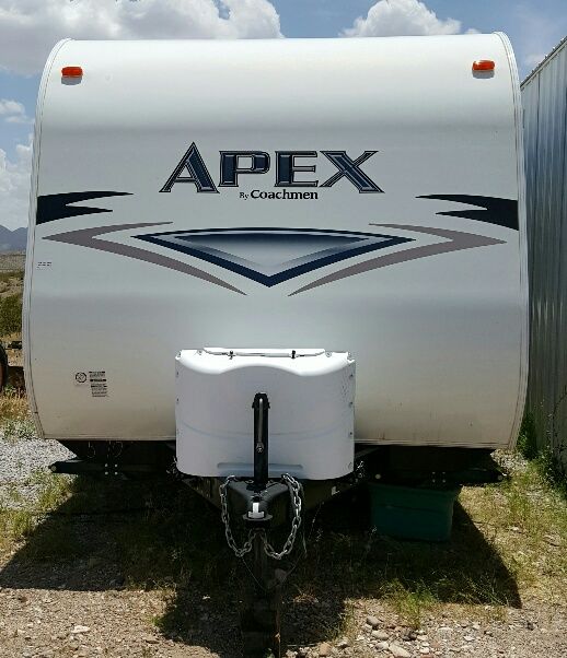
I am looking to a three sided panel system to enclose the front of the trailer. A 3 ft wide panel 5 ft 4 inches tall in front of the propane tanks and two panels angling in to the corners on each side capped by a 25 degree slopping roof panel. A aerodynamic shroud around the AC unit on the roof might be good to do also.
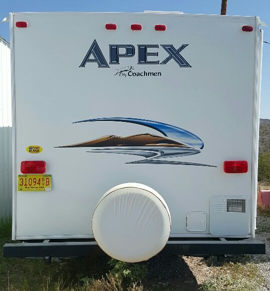
On the back I need a second bracket U bolted to the bumper like the spare tire bracket is. I would move the spare tire bracket closer to the outside edge of the trailer. Then I would construct a four sided open boat tail sticking out 2 ft. The sides would angle in at 10 degrees and the top would be a 25 degree angle.
__________________


Last edited by aerostealth; 06-25-2015 at 10:23 PM..
|
|
|

|
|
The Following 2 Users Say Thank You to aerostealth For This Useful Post:
|
|
 Today Today
|
|
|
|
 Other popular topics in this forum...
|
|
|
|
 06-25-2015, 11:09 PM
|
#2 (permalink)
|
|
EcoModding Lurker
Join Date: Sep 2011
Location: california
Posts: 49
Thanks: 1
Thanked 12 Times in 10 Posts
|
Looking forward to seeing what you do and to what result. Do you have a profile pic of the trailer and the truck?
Travis..
|
|
|

|
 06-26-2015, 09:23 AM
|
#3 (permalink)
|
|
Aero Deshi
Join Date: Jan 2010
Location: Vero Beach, FL
Posts: 1,065
Thanks: 430
Thanked 669 Times in 358 Posts
|
I see how you want to improve the airflow coming off the back of your trailer. But when you say you want the top to slope at 25°, it seems as though you have misinterpreted some of the information about basic aerodynamics here on ecomodder.
Here is my suggestion, do whatever you need to do in order to radius the shape. On top I would not try to go much past a 15° angle overall which is what my illustration shows here. Also radius the sides. This will give your modification the best chance to work well. If you just go straight to 25° (The red line on the pic here), I really don't think it will help much at all. Even if optimized however, I would not expect a 2 foot extension to return more than a 3-5% gain on mpg.
Hope this helps, I'd include more stuff but I gotta run now.
 |
|
|

|
|
The Following User Says Thank You to ChazInMT For This Useful Post:
|
|
 06-26-2015, 10:47 AM
|
#4 (permalink)
|
|
Master EcoModder
Join Date: Dec 2014
Location: Radium Springs, NM
Posts: 465
Thanks: 2
Thanked 528 Times in 278 Posts
|
Phil Knox is sending me a boat tail paper and I got the 25 degree figure for the top panel from him.
Even I thought it was extreme. I am waiting on the paper. May not do any of this work until fall so plenty of time.
__________________


|
|
|

|
 06-26-2015, 04:15 PM
|
#5 (permalink)
|
|
Master EcoModder
Join Date: Jan 2008
Location: Sanger,Texas,U.S.A.
Posts: 16,532
Thanks: 24,520
Thanked 7,436 Times in 4,817 Posts
|
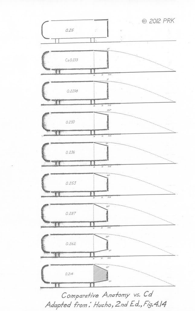
25-degrees
It's from the Ahmed body of research.It's simple to construct.Simple materials.
It's been independently verified by at least two other investigators,so it's a 'known quantity.'
*25 on top
*10 on the sides
*10 for the diffuser if included
Bottom image in table
__________________
Photobucket album: http://s1271.photobucket.com/albums/jj622/aerohead2/
|
|
|

|
|
The Following 2 Users Say Thank You to aerohead For This Useful Post:
|
|
 06-26-2015, 08:40 PM
|
#6 (permalink)
|
|
Banned
Join Date: Oct 2009
Location: Fort Worth, Texas
Posts: 2,442
Thanks: 1,422
Thanked 737 Times in 557 Posts
|
As reference, 12-22 degrees radius was the range used by the aero aluminum TTs on wall edges, top & bottom, (to turn the corners) from WWII to about 1990 (even when some exceeded that).
|
|
|

|
 06-26-2015, 10:03 PM
|
#7 (permalink)
|
|
Aero Deshi
Join Date: Jan 2010
Location: Vero Beach, FL
Posts: 1,065
Thanks: 430
Thanked 669 Times in 358 Posts
|
So what is the difference between the bottom image and the one just up from it? Also, it seems to me like a bottom diffuser area has come into play that was not mentioned earlier. The test samples also seem to be missing a tow vehicle which I'm certain would have an affect on the system here. Sorry, but a 25° top drop angle flies in the face of everything I've come to understand about aerodynamics these past few years.
I'd love to know what is different between the last 2 drawings that makes a .05 difference in the Cd.
|
|
|

|
 06-27-2015, 12:17 AM
|
#8 (permalink)
|
|
Master EcoModder
Join Date: Dec 2014
Location: Radium Springs, NM
Posts: 465
Thanks: 2
Thanked 528 Times in 278 Posts
|
I am having a little trouble interpreting the Hucho drawing too? I think that the very bottom drawing means the two sides and the bottom are tapered in 10 degrees, and the top is at 25 degrees. The second drawing from the bottom may just have strait sides? Aerohead needs to interpret this drawing for us. As I understand it, curved sides are best, but when using flat panels these angles are required to approximate what curved panels would do.
__________________


|
|
|

|
 06-27-2015, 12:27 PM
|
#9 (permalink)
|
|
Master EcoModder
Join Date: Jan 2008
Location: Sanger,Texas,U.S.A.
Posts: 16,532
Thanks: 24,520
Thanked 7,436 Times in 4,817 Posts
|
difference
Quote:
Originally Posted by ChazInMT

So what is the difference between the bottom image and the one just up from it? Also, it seems to me like a bottom diffuser area has come into play that was not mentioned earlier. The test samples also seem to be missing a tow vehicle which I'm certain would have an affect on the system here. Sorry, but a 25° top drop angle flies in the face of everything I've come to understand about aerodynamics these past few years.
I'd love to know what is different between the last 2 drawings that makes a .05 difference in the Cd.
|
The bottom image is the only configuration which includes plan-taper of the boat tail sides.All the rest are just parallel.
__________________
Photobucket album: http://s1271.photobucket.com/albums/jj622/aerohead2/
|
|
|

|
|
The Following User Says Thank You to aerohead For This Useful Post:
|
|
 06-27-2015, 12:39 PM
|
#10 (permalink)
|
|
Master EcoModder
Join Date: Jan 2008
Location: Sanger,Texas,U.S.A.
Posts: 16,532
Thanks: 24,520
Thanked 7,436 Times in 4,817 Posts
|
interpret
Quote:
Originally Posted by aerostealth

I am having a little trouble interpreting the Hucho drawing too? I think that the very bottom drawing means the two sides and the bottom are tapered in 10 degrees, and the top is at 25 degrees. The second drawing from the bottom may just have strait sides? Aerohead needs to interpret this drawing for us. As I understand it, curved sides are best, but when using flat panels these angles are required to approximate what curved panels would do.
|
*yes,the sides on the bottom image have 10-degree plan-taper into the page.It's the only configuration tested with plan-taper.
*there's nothing in the literature comparing this design to that of one with curves.
*all we can infer,is that if we build exactly as shown,we can expect these kinds of results.
--------------------------------------------------------------------------
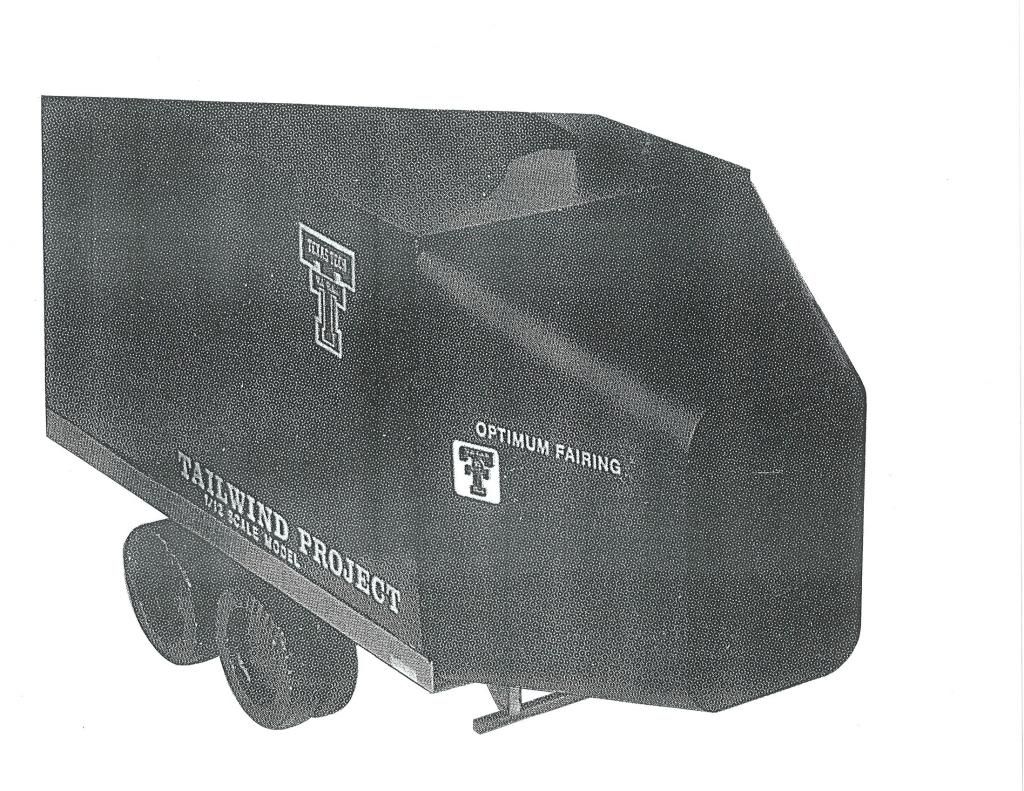
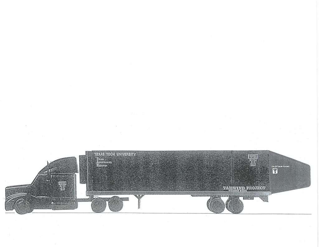
*The GM 'OPTIMIZED' boat tail (classified) has progressive edge radii at all intersections and is superior as it produces zero vorticity,but would require maybe 5-X fabrication time.
__________________
Photobucket album: http://s1271.photobucket.com/albums/jj622/aerohead2/
Last edited by aerohead; 06-27-2015 at 12:41 PM..
Reason: add image
|
|
|

|
|
The Following 2 Users Say Thank You to aerohead For This Useful Post:
|
|
|