 12-16-2014, 09:47 AM
|
#41 (permalink)
|
|
Aero Deshi
Join Date: Jan 2010
Location: Vero Beach, FL
Posts: 1,065
Thanks: 430
Thanked 669 Times in 358 Posts
|
Thee Template © ®™ is simply the shape the air molecules want to follow for optimum return to the place where they were before you tried to ram them with your vehicle.
|
|
|

|
 Today Today
|
|
|
|
 Other popular topics in this forum...
|
|
|
|
 12-16-2014, 07:23 PM
|
#42 (permalink)
|
|
EcoModding Apprentice
Join Date: Aug 2014
Location: Adelaide, Australia
Posts: 120
Thanks: 53
Thanked 53 Times in 32 Posts
|
Apologies for the annoyed tone and partial off-topic-ness, but
More like a handy approximation of "the shape the air molecules want to follow for optimum return to the place where they were before you tried to ram them with your vehicle" given air flow that:
* is attached flow along the upper surface
* has a given amount of initial turbulence before you 'ram it with your vehicle'
* transitions to turbulent at a particular point (about 30% length I think, just looking at it?)
And the vehicle
* is close to a particular cross sectional shape
* is travelling within a particular speed range
* has a non ideal - but reasonably smooth - surface finish
In order to
* prevent premature flow separation (i.e. before a 'kamm' style cut-off) and
* reduce drag by achieving decent pressure recovery (given all the other assumptions and conditions)
Assuming
* form (pressure) drag is dominant over skin (friction) drag
* flow hasn't been tripped to turbulent too early
* flow can't be kept laminar much more than typical
* probably a bunch of other stuff I've missed here...
Sorry if I sound frustrated there, it just irks me a little that it keeps getting applied to everything, when the reality is a whole lot more complex. It's a great tool for vehicle modding which I wouldn't be surprised if it gets you within near-as-makes-no-difference of optimal when adding a kammback to your sedan, and a decent approximation of what you want the air to be doing in a general sense, but the "grand unified theory of fluid dynamics" it ain't.
Last edited by Madact; 12-16-2014 at 08:26 PM..
|
|
|

|
|
The Following User Says Thank You to Madact For This Useful Post:
|
|
 12-16-2014, 08:38 PM
|
#43 (permalink)
|
|
Master EcoModder
Join Date: Aug 2012
Location: northwest of normal
Posts: 29,211
Thanks: 8,297
Thanked 9,056 Times in 7,485 Posts
|
That about covers it. Certainly it is the right subforum, if not the right thread.
The easiest way to falsify The Sacred Template is to look at the front and rear views. Few vehicles have a semi-circular cross-section.
Not that I haven't given it my best shot:
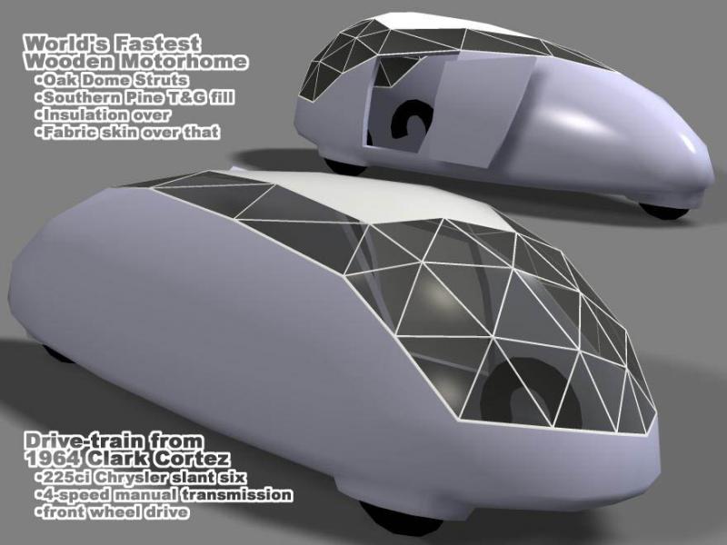
What's worst is ignoring the curve and using a break followed by a 12 flat angle. |
|
|

|
 12-16-2014, 09:41 PM
|
#44 (permalink)
|
|
Aero Deshi
Join Date: Jan 2010
Location: Vero Beach, FL
Posts: 1,065
Thanks: 430
Thanked 669 Times in 358 Posts
|
Quote:
Originally Posted by Madact

but the "grand unified theory of fluid dynamics" it ain't.
|
True Dat.
I think as well as the things you mentioned regarding the layer of air within 2 inches of the vehicle, the template prevents the gross swirls of air extending out a couple of yards around and many 10's to 100's of yards behind the the vehicle as well. I really think the template serves its biggest gains in minimizing the long persistent turbulent wake that is being dragged about by any particular vehicle.
We ram through the air, the more we disrupt it and make it swirl about to and fro, the longer it stays in motion after we pass, then the more energy we have put into the air to make it move, and the less efficient we'll be.
The "whole lot more complex" thing you mention has to do with the fact that having the template overlayed and followed on one aspect of the vehicle does not the uber efficient shape make if other aspects are not considered.
It would be real simple if we lived in a 2D world, the template would always be the aspiration to achieve. But that silly ol 3D thing really takes us from a X + Y = Z formula to an equation so complex, the most powerful computers we have are not able to accurately predict whats going to happen when any variable is changed on a vehicle.
Your "* Flow hasn't been tripped turbulent too early" line is the only issue I have with what you said. On vehicles in ground effect, laminar flow is never assumed to exist anywhere ever, there are only degrees of turbulent.
Handy Approximation.....I'll take 2 at that price.
Check please!
BTW I hope you realize my "Thee Template © ®™" was meant to be taken with 3 lumps of sarcasm. |
|
|

|
 12-17-2014, 06:02 PM
|
#45 (permalink)
|
|
Master EcoModder
Join Date: Jan 2008
Location: Sanger,Texas,U.S.A.
Posts: 16,453
Thanks: 24,487
Thanked 7,419 Times in 4,807 Posts
|
unified
Quote:
Originally Posted by Madact

Apologies for the annoyed tone and partial off-topic-ness, but
More like a handy approximation of "the shape the air molecules want to follow for optimum return to the place where they were before you tried to ram them with your vehicle" given air flow that:
* is attached flow along the upper surface
* has a given amount of initial turbulence before you 'ram it with your vehicle'
* transitions to turbulent at a particular point (about 30% length I think, just looking at it?)
And the vehicle
* is close to a particular cross sectional shape
* is travelling within a particular speed range
* has a non ideal - but reasonably smooth - surface finish
In order to
* prevent premature flow separation (i.e. before a 'kamm' style cut-off) and
* reduce drag by achieving decent pressure recovery (given all the other assumptions and conditions)
Assuming
* form (pressure) drag is dominant over skin (friction) drag
* flow hasn't been tripped to turbulent too early
* flow can't be kept laminar much more than typical
* probably a bunch of other stuff I've missed here...
Sorry if I sound frustrated there, it just irks me a little that it keeps getting applied to everything, when the reality is a whole lot more complex. It's a great tool for vehicle modding which I wouldn't be surprised if it gets you within near-as-makes-no-difference of optimal when adding a kammback to your sedan, and a decent approximation of what you want the air to be doing in a general sense, but the "grand unified theory of fluid dynamics" it ain't.
|
*The 'Template' is a composite of 'solutions' recommended for road vehicle aerodynamic drag reduction,which by definition is pressure drag reduction achieved through elimination of flow separation,and is applicable to any passenger car manufactured after 1985,although it will work for 1975 Volkswagens.
*Attached flow on the roof is presumed.
*Ambient air is turbulent.
*Transition to full turbulent boundary layer occurs within the first 2-inches.
*The cross-sectional profile of any post-1984 automobile body will suffice.
*Operational velocities up to 250-mph under standard atmospheric conditions would be applicable.
*Any automobile manufactured in the last hundred years has an 'ideal' surface finish.
*If the 'Template' contour is applied as specified,separation is impossible.
*The premise of the 'Template' is to provide the proper rate of flow deceleration which enables pressure recovery.
*Pressure drag is always the dominant component of profile drag and,again,it's reduction or elimination is the premise of aerodynamic streamlining.
*The flow always trips itself to a TBL within the first 2-inches of body length.
If there is separation,then the TBL lifts away from the body's surface, inducing turbulence.If the flow does not reattach,then this will be the beginning of the wake.
*The laminar inviscid flow remains intact unless separation occurs.The variety of body styles might preclude the use of 'typical' when addressing flow.
------------------------------------------------------------------------
*If you'd like to see the full scientific derivation of the Aerodynamic Streamlining Templates,I invite you to read the thread.
*And while reality IS complex,the AST respects the complexities of reality as expressed in empirical scientific examinations for 92-years.
__________________
Photobucket album: http://s1271.photobucket.com/albums/jj622/aerohead2/
|
|
|

|
 12-18-2014, 05:10 AM
|
#46 (permalink)
|
|
Master EcoModder
Join Date: Jul 2010
Location: Belgium
Posts: 4,683
Thanks: 178
Thanked 652 Times in 516 Posts
|
Quote:
Originally Posted by aerohead

The concept has been demonstrated in aviation since the 1920s,with blown slots on wings,in Ludwig Prandtl's research.
There are STOL aircraft which use it today.
|
Blown flaps (front and rear of the wings) have been used on many aircraft - don't have to be STOL designs.
Taking bleed air from jets.
Or using the engine exhausts as a blower above or more traditionally, under the wings.
Quote:
|
Historically,the pump absorbs more energy than is saved with the slot.Not an issue with military aircraft.
|
Oh, it is, but there's power aplenty in the take-off phase to spare some bleed air.
Especially if it increases lift when that's what you really want.
On landing, it's just a function of not throttling back the power as much which is also OK as higher power settings tend to improve throttle response, which was sluggish in the early days.
Then dump the power by creating more drag (and lift along with it).
Quote:
Originally Posted by Hypermiler1995

(I wish I could post pics correctly  ) I drew a car that used ducts through the side to guide air from the nose, around the side, and out the back into the wake without boattailing.  But it takes away from the space in the car, would cause some drag itself due to curves the air would go through, and its totally a nightmare for the back glass |
Ducting doesn't really work - it's essentially the complicated and expensive way to reducing frontal area.
"Wetted" area is increased
You get interference drag between the various "pods" that reduces or eliminates whatever is gained.
That's on top of the issues you already pointed out.
__________________
Strayed to the Dark Diesel Side

|
|
|

|
|
The Following User Says Thank You to euromodder For This Useful Post:
|
|
 12-18-2014, 06:08 PM
|
#47 (permalink)
|
|
Master EcoModder
Join Date: Jan 2008
Location: Sanger,Texas,U.S.A.
Posts: 16,453
Thanks: 24,487
Thanked 7,419 Times in 4,807 Posts
|
double-box
Quote:
Originally Posted by Madact

Looking closely at the results from those makes me wonder if there'd be merit to a 'double box' arrangement: On the outer edge (or at a very small offset), have a very shallow box, either straight or angled in, with the conventional 'offset cavity' inside it (blue). The shallow outer box (or 'lip' I guess) might even allow a splitter (red) to be more effective, though my money would be on the inner box cavity.
Goes against the KISS principle of course  but I'm thinking if rounded edges is bad, sharp 90 degree edges is better, maybe sharper-than-90-degree edges may be better still? Unfortunately I'm not in possession of a large truck fitted with precision instrumentation to try it out 
 |
It's just my opinion,but I think all three would have a shot at drag reduction.
You've got this large turbulent wake
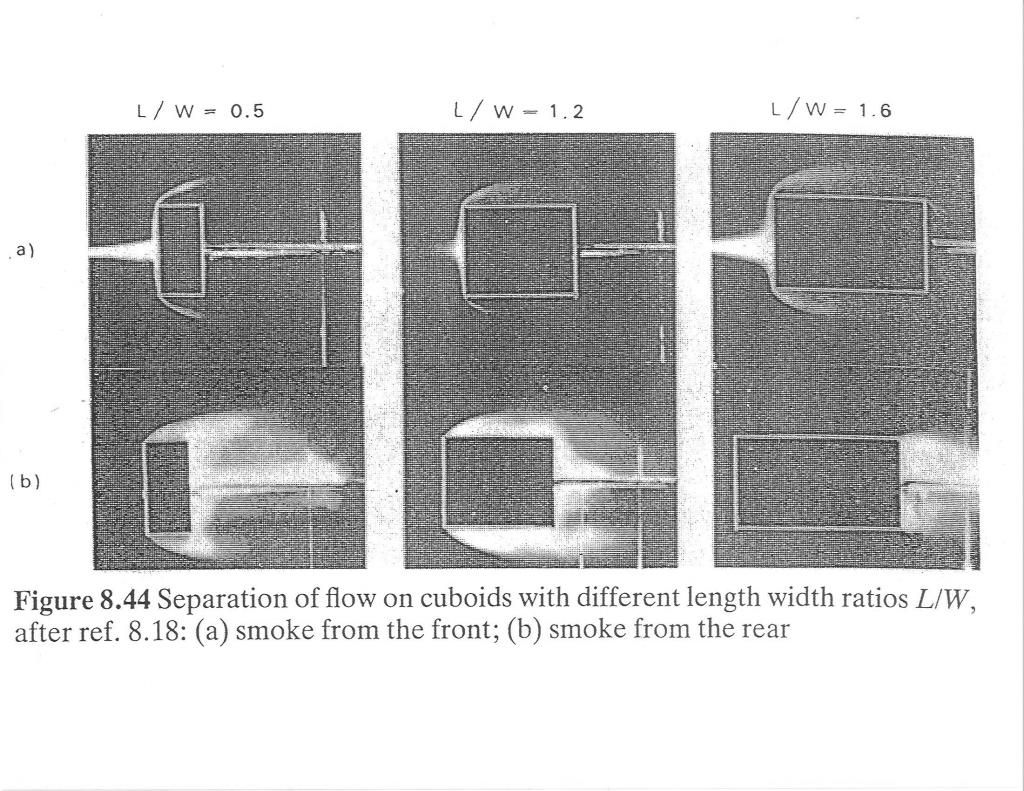
The major eddies might be burst and broken up by the double-box fins and splitter,creating a more homogeneous wake of smaller eddies. 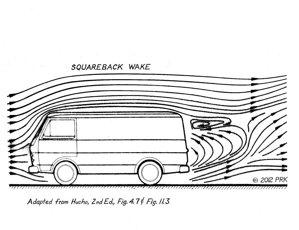
Any vorticity captured at the 1st box would help pull the flow in.I don't know about the base pressure though.The entire base pressure is governed by the pressure at the point of separation,and we're not really altering this.
--------------------------------------------------------------------------
If you have access to a university lab,you could throw some money at the engineering department,and sponsor some undergrad or graduate study,either in CFD or a scale wind tunnel.They might already have a truck model,and then they'd only have to fab up the fins.
--------------------------------------------------------------------------
The 'system' would be light.Relatively inexpensive.It probably wouldn't freak out the truckers who'd have to deal with it on a day to day basis.
Depending upon the test results,someone could decide if it's a viable option to competing technologies.
It would need to collapse if struck from the rear,or insurance companies would be all over it.
We can never have TOO MUCH information to work with. 
Here is Mair's boat tail recommendation as a comparison.You can see how he handles the TBL with kid gloves until the cambered flow and momentum is fully established.
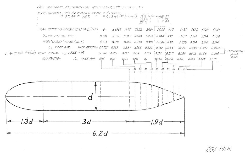
Here is an abbreviation of Mair's research model,with the constant-velocity portion of the body removed.
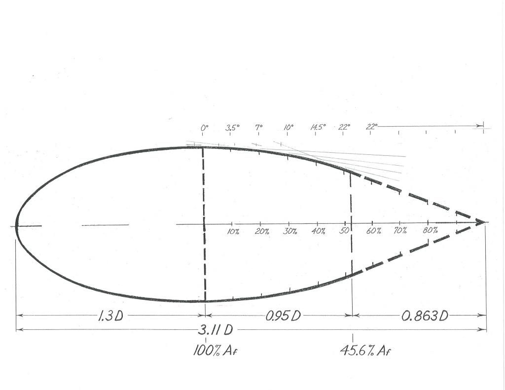
Another comparison is the dimpled golf ball with TBL and delayed separation.If this gentle aft-body contour is 'scaled' up,the separation point can be moved rearward indefinitely as a function of radius.

Again,the TBL is allowed only a very gentle pressure gain.
The shape of the wake itself suggests a contour which the air would respect
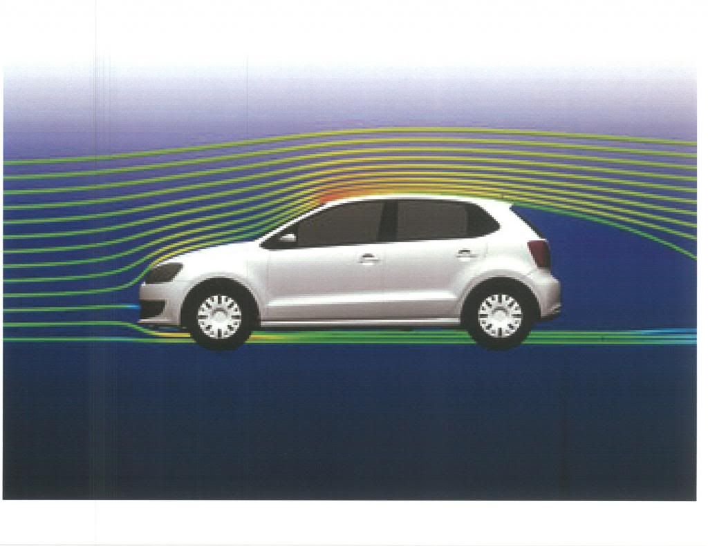
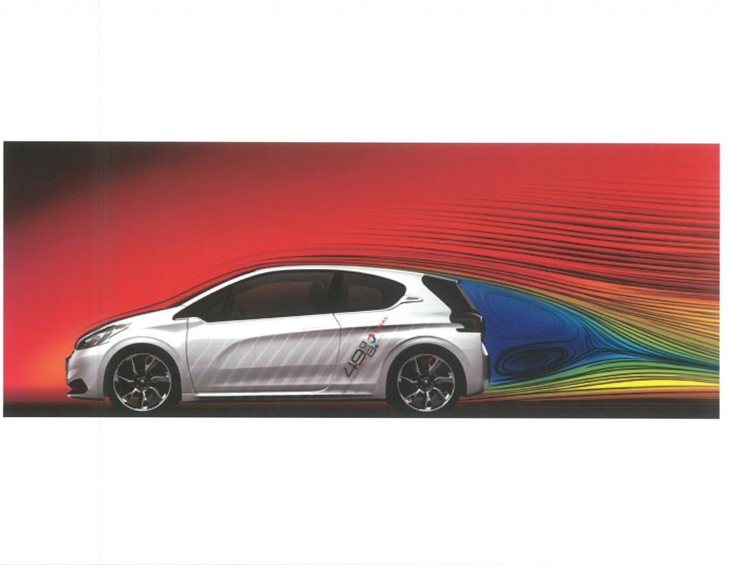
You can see how the 1-liter VW takes advantage of the profile

I did find the Continuum Dynamics image (This is the 18-wheeler tested at NASA Ames Research Center in 1989) and the fins are placed very 'shallow' with respect to the trailer box.I don't have it scanned.And it's a very small image.
__________________
Photobucket album: http://s1271.photobucket.com/albums/jj622/aerohead2/
Last edited by aerohead; 12-23-2014 at 04:25 PM..
Reason: add images
|
|
|

|
|
The Following 2 Users Say Thank You to aerohead For This Useful Post:
|
|
 01-05-2015, 11:17 PM
|
#48 (permalink)
|
|
EcoModding Apprentice
Join Date: Nov 2014
Location: missouri
Posts: 209
Thanks: 59
Thanked 62 Times in 34 Posts
|
bump!
1976 BMW 3.5 Csl turbo

note the roof deflector
__________________
"Ignorance is bliss, but only for the ignorant"-Hypermiler1995
|
|
|

|
 01-06-2015, 12:26 AM
|
#49 (permalink)
|
|
Not Doug
Join Date: Jun 2012
Location: Show Low, AZ
Posts: 12,289
Thanks: 7,289
Thanked 2,238 Times in 1,728 Posts
|
Quote:
Originally Posted by Hypermiler1995

|

|
|
|

|
 01-06-2015, 08:46 AM
|
#50 (permalink)
|
|
Master EcoModder
Join Date: Jul 2011
Location: Ann Arbor, Michigan
Posts: 4,201
Thanks: 136
Thanked 2,821 Times in 1,980 Posts
|
Quote:
Originally Posted by Madact

.....Sorry if I sound frustrated there, it just irks me a little that it keeps getting applied to everything, when the reality is a whole lot more complex. It's a great tool for vehicle modding which I wouldn't be surprised if it gets you within near-as-makes-no-difference of optimal when adding a kammback to your sedan, and a decent approximation of what you want the air to be doing in a general sense, but the "grand unified theory of fluid dynamics" it ain't.
|
I agree, and a good 2D profile is better than nothing.
Turning a blind eye to the cross section or 3D aspects of the template has always been a sensitive issue with me as well.
Quote:
Originally Posted by Hypermiler1995

|
Those things work, at least as installed on my pick-up truck.
Just a 1/4" open 45 degree beveled slot at the trailing roof edge does wonders at redirecting surface air flow. See last link in my signature below.
__________________
George
Architect, Artist and Designer of Objects
2012 Infiniti G37X Coupe
1977 Porsche 911s Targa
1998 Chevy S-10 Pick-Up truck
1989 Scat II HP Hovercraft
You cannot sell aerodynamics in a can............
|
|
|

|
|