Go Back   EcoModder Forum > EcoModding > Fossil Fuel Free
Register Now
 Register Now
 

Reply  Post New Thread
 
Submit Tools LinkBack Thread Tools
Old 08-03-2015, 09:00 PM   #51 (permalink)
Master EcoModder
 
Join Date: Jun 2010
Location: Australia
Posts: 253

Delivery 'Boy - '86 Suzuki Mighty Boy
90 day: 37.15 mpg (US)

SkipSwift - '13 Suzuki Swift GL
90 day: 35.44 mpg (US)
Thanks: 0
Thanked 53 Times in 42 Posts
actually I just realised that on every car I have seen recently, it's the airflow through the heater core that is controlled for temperature adjustment, not the temp of the heater core itself. Existing temperature controls would remain in most cases even with the ceramic core

__________________


Quote:
Originally Posted by Crazyrabbit
In God we trust. All others: bring data
  Reply With Quote
Alt Today
Popular topics

Other popular topics in this forum...

   
Old 02-12-2016, 06:50 AM   #52 (permalink)
Dreamer
 
Join Date: Nov 2013
Location: Australia
Posts: 350
Thanks: 95
Thanked 214 Times in 151 Posts
Quote:
Originally Posted by BLSTIC View Post
...Existing temperature controls would remain in most cases even with the ceramic core
Yes, as the air flow increases the ceramic element will cool which causes more current to flow and the element will return to its equilibrium temperature. The higher the air flow the higher the current flow to maintain the temperature but it is all automatic.
It does seem like the simplest, cheapest, best performing solution.
It also makes a nice test load for the batteries as it is working at full pack voltage and is simple to control.
  Reply With Quote
Old 02-12-2016, 10:56 AM   #53 (permalink)
Dreamer
 
Join Date: Nov 2013
Location: Australia
Posts: 350
Thanks: 95
Thanked 214 Times in 151 Posts
Slow Progress but still progress.

The coupler between the electric motor and the gearbox has been completed.

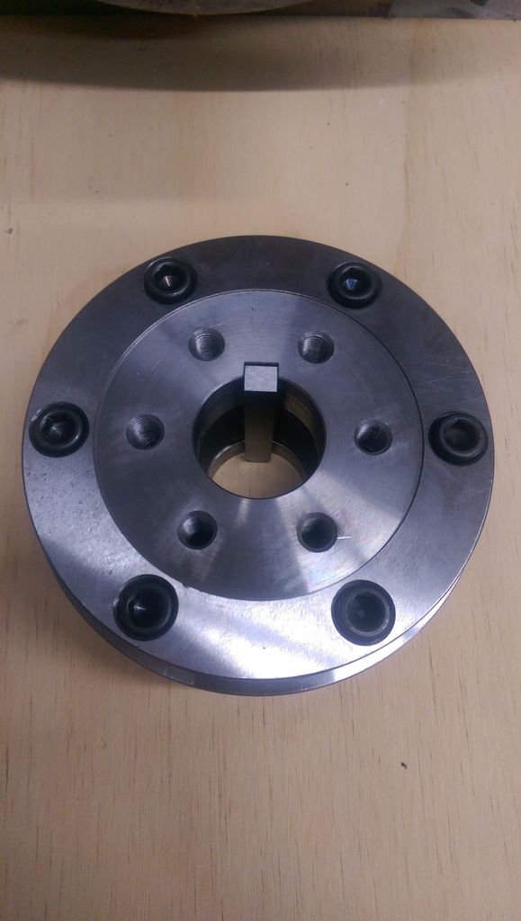
Here is a picture of the parts.


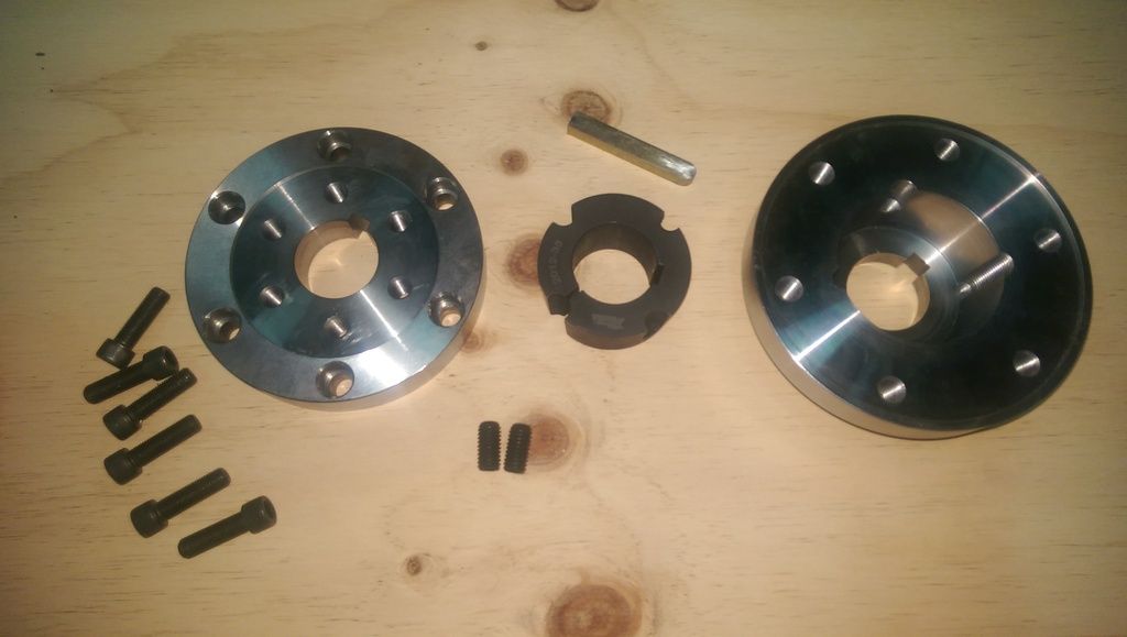
I am retaining the clutch and flywheel so this adaptor is just to attach the flywheel to the motor shaft. Previously the flywheel connected to the end of the crankshaft on the ICE engine.
The adaptor has three parts. A keyed back plate that has the tapered void to house the taper lock. (rightmost in image) Then there is the taper lock itself, also keyed. (center of image) Then there is the front plate. (leftmost in image) The front plate is also keyed. The front plate is used to adapt the bolt placement on the flywheel which has a small distance from center to the larger distance from center bolt spacing of the back plate. The large distance from center is required on the back plate due to the large diameter of the taper lock.

This is not the final assembly picture, just a dry fit to see if there are any issues.

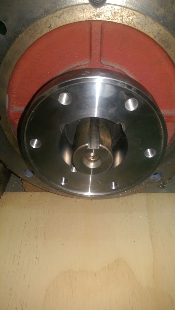
Back plate in place on the motor output shaft.


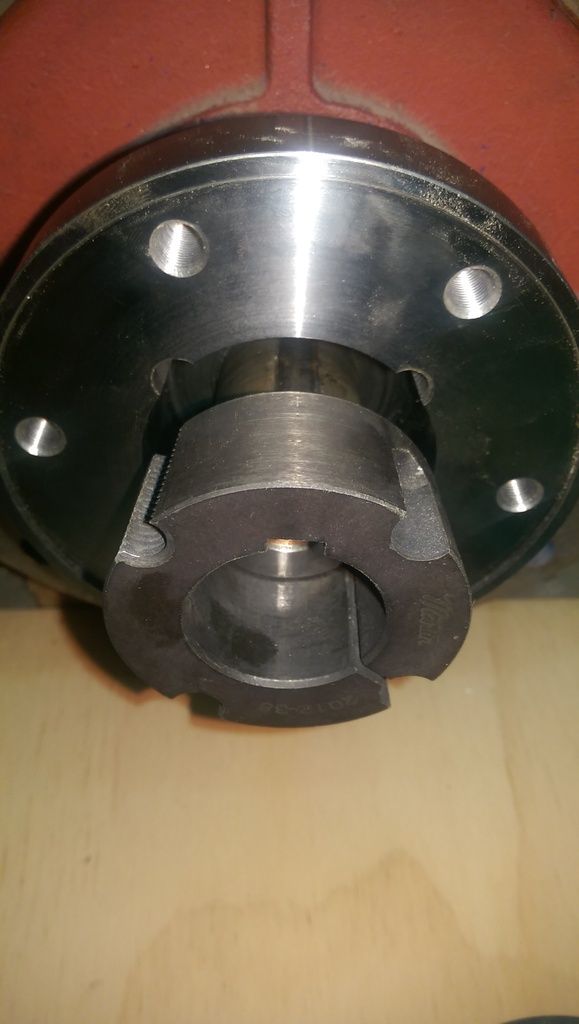
Next the taper lock.
The taper lock constricts as it is pulled down into the back plate by grub screws.


Here is a view of the parts off of the shaft so it is easier to see. The taper lock is pulled down into into the back plate. You can also see the key that runs through all three pieces of the adaptor.


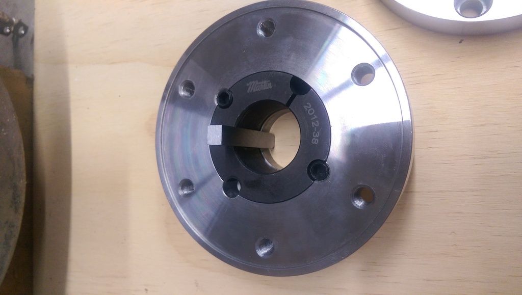
Then the front plate is attached using 6 recessed hex head bolts.


The front plate has 6 threaded bolt holes that match the spacing on the flywheel. The flywheel attaches to the front plate using the same bolts that previously attached it to the crankshaft.


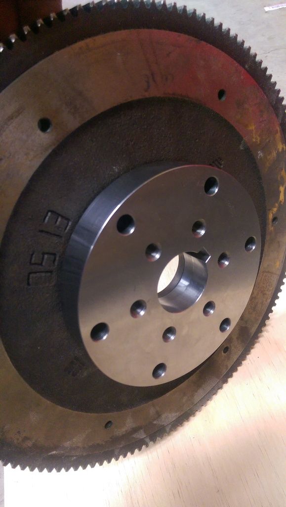
So the flywheel is held by a key through all three parts as well as a large taper lock.
I don't foresee any slippage.

Now that the shaft to flywheel adaptor is built we can look at making the adaptor plate that will connect the motor casing to the gearbox casing. With the flywheel attached to the motor we now know how thick to mill the adaptor plate so that the flywheel ends up in the same position it was in with the ICE engine.

Then once that is done and the gearbox and motor are joined we can create the engine mount to suit the motors final position.
  Reply With Quote
The Following User Says Thank You to Astro For This Useful Post:
MPaulHolmes (02-12-2016)
Old 02-12-2016, 12:07 PM   #54 (permalink)
PaulH
 
MPaulHolmes's Avatar
 
Join Date: Feb 2008
Location: Maricopa, AZ (sort of. Actually outside of town)
Posts: 3,832

Michael's Electric Beetle - '71 Volkswagen Superbeetle 500000
Thanks: 1,368
Thanked 1,202 Times in 765 Posts
This is a huge step!! And you are doing it right. There's really not THAT much that you have to do to get it driveable. Stick a motor on, stick some batteries on your lap, and drive away.
__________________
kits and boards
  Reply With Quote
The Following User Says Thank You to MPaulHolmes For This Useful Post:
Astro (02-12-2016)
Old 02-12-2016, 10:40 PM   #55 (permalink)
Dreamer
 
Join Date: Nov 2013
Location: Australia
Posts: 350
Thanks: 95
Thanked 214 Times in 151 Posts
Quote:
Originally Posted by MPaulHolmes View Post
This is a huge step!! And you are doing it right. There's really not THAT much that you have to do to get it driveable. Stick a motor on, stick some batteries on your lap, and drive away.
It's an AC motor so it needs Paul's Magic Motivator between the batteries and the motor.
The coupler is the part that always had me nervous. Electrical stuff is a bit easier. Especially to modify, enhance, relocate etc. The mechanical stuff needs to be spot on and you won't know you have got it wrong until you are nearly finished. A bit of misalignment may not be obvious to look at. It might not even show up in stationary tests but then when you get on the highway and the engine bay sounds like it is holding a jackhammer captive then it is a big problem.
So we went a bit overboard on the coupler to get everything aligned, balanced and strong. I think it is probably a bit (lot) over engineered.
If you don't have the engineering background to correctly model something then just work out what seems reasonable and then double it.

  Reply With Quote
Reply  Post New Thread


Tags
barina


Powered by vBulletin® Version 3.8.11
Copyright ©2000 - 2024, vBulletin Solutions Inc.
Content Relevant URLs by vBSEO 3.5.2
All content copyright EcoModder.com