well, crap!
Note to self - remove oscilloscope probe grounding wire if not using the isolation transformer!
I was testing my setup on my vehicle pack. It's pretty much done, ready to go. I figured out a way to do isolated voltage measurement, written the appropriate code, and had it working on the resistive load - would hold a voltage +/- a few tenths of a volt.
I wanted to look at the waveform on the real application, so lugged out my isolation transformer, wired everything up and turned it on. Everything looked good - held current constant under 3A even though the inductor had discontinuous current, above 3A entered continuous conduction and the waveform looked pretty clean. Cool.
My isolation transformer is small, so I can't draw much power. I unplugged it, turned off the scope, and plugged the charger up to the 240AC.
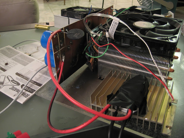
POP! Blinding sparks! Ugh... Maybe it's ok - I know the concept works and I think I have an idea for a better layout using plus247 sized devices that'll be smaller and more organized.
What looks like a shadow on the plexiglass is really black soot from the mosfet...

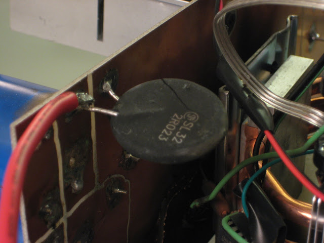
The inrush current limiter cracked...

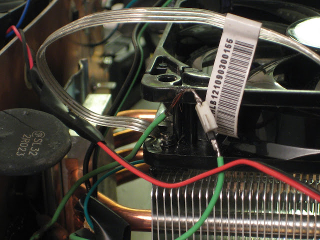
That grean wire is where the probe ground connected, Current flowed from the leads, through the board, through this green wire and to ground via the probe ground. Notice it's a little melted...

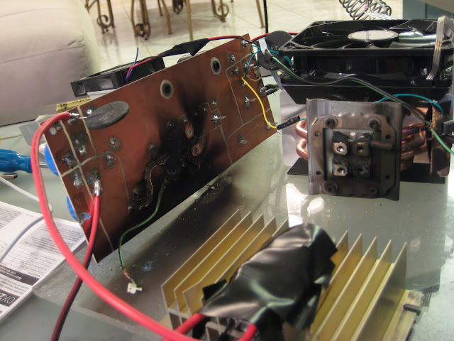
More blackness. The copper seemed to vaporize a little along one of the lines I milled.

The vaporized copper is more visible... I think that the mosfet and current limiter are the only casualties, but I don't think I'd reuse the board only because I have a new layout planned.
