07-27-2009, 08:18 PM
|
#151 (permalink)
|
|
home of the odd vehicles
Join Date: Jun 2008
Location: Somewhere in WI
Posts: 3,892
Thanks: 508
Thanked 868 Times in 654 Posts
|
Quote:
Originally Posted by NiHaoMike

A capacitive voltage doubler is more efficient than either PFC or a step up transformer.
|
I have been trying to find a solid state simple capacitive voltage transformer schematic.
My goal a simple 50/50 duty cycle flip flop going between capacitors hooked to source in series then latching load in parallel (half)
Do you know of any schematics for such a beasty? I want it as simple as possible so I can just choose the rate based on the capacity of the cap.
I have been told a mosfet can't operate in that way.
Cheers
Ryan
|
|
|

|
 Today Today
|
|
|
|
 Other popular topics in this forum...
|
|
|
|
|
07-27-2009, 09:28 PM
|
#152 (permalink)
|
|
Master EcoModder
Join Date: Sep 2008
Location: Texas
Posts: 632
Thanks: 0
Thanked 26 Times in 24 Posts
|
File:Bridge voltage doubler.svg - Wikipedia, the free encyclopedia
Ignore the transformer since there isn't one in our application. Note that you can use a common bridge rectifier and a switch to select between 120v and 240v operation. (It will operate as a voltage doubler for 120v operation and a bridge rectifier for 240v operation. In 120v mode, parallel the two diode pairs to load balance them.)
__________________
If America manages to eliminate obesity, we would save as much fuel as if every American were to stop driving for three days every year. To be slender like Tiffany Yep is to be a real hypermiler...
Allie Moore and I have a combined carbon footprint much smaller than that of one average American...
|
|
|
|
|
08-27-2009, 11:44 AM
|
#153 (permalink)
|
|
EcoModding Lurker
Join Date: Jul 2009
Location: Seattle
Posts: 18
Thanks: 0
Thanked 1 Time in 1 Post
|
Quote:
Originally Posted by jyanof
Actually, instead of a simple boost stage, what I really want to do is add a PFC stage. It'll act a boost stage and boost any input voltage from 120 to 240AC to ~400VDC, but do so such that there is close to unity power factor.
|
What's the advantage for a residential customer to have unity PF (other than bragging rights, which is good enough for me)? I know that industrial customers are billed based on some aggregate of their facility PF, but not residential customers. I've heard arguements that active PFC usually decreases the system efficiency because there's another transistor (or FET or IGBT) dissipating power.
Last edited by vwdevotee; 08-27-2009 at 01:12 PM..
|
|
|
|
|
08-27-2009, 01:10 PM
|
#154 (permalink)
|
|
Joe
Join Date: Feb 2009
Location: phx
Posts: 260
Thanks: 0
Thanked 48 Times in 38 Posts
|
Quote:
Originally Posted by vwdevotee
What's the advantage for a residential customer to have unity PF (other than bragging rights, which is good enough for me)? I know that industrial customers are billed based on some aggregate of their facility PF, but not residential customers. I've heard arguements that active PFC usually decreases the system efficiency because there's another transistor (or FET or OGBT) dissipating power.
|
Yes, active PFC will introduce more inefficiencies for precisely those reasons. However, from what I understand, PFC allows the user to draw more power from the wall circuit.
Low PF circuits may have a low average current, but the instantaneous current may be spiking higher or near the rated current for the breaker. Hence, you may be only to use half the power of a given outlet before the breaker trips. Not too much of an issue if you're on a 240V 30A outlet, but more of an issue if you're using a 120V 20A outlet and want to charge in a reasonable amount of time.
Another advantage would be plugging into 120V or 240V without having to change any settings on the charger (maybe output current, if there's not an input current sensor)
Stepping back from the trees, there's also the perspective from your electricity provider. From wikipedia:
"The significance of power factor lies in the fact that utility companies supply customers with volt-amperes, but bill them for watts. Power factors below 1.0 require a utility to generate more than the minimum volt-amperes necessary to supply the real power (watts). This increases generation and transmission costs. For example, if the load power factor were as low as 0.7, the apparent power would be 1.4 times the real power used by the load. Line current in the circuit would also be 1.4 times the current required at 1.0 power factor, so the losses in the circuit would be doubled (since they are proportional to the square of the current). Alternatively all components of the system such as generators, conductors, transformers, and switchgear would be increased in size (and cost) to carry the extra current." |
|
|
|
|
08-28-2009, 12:30 AM
|
#155 (permalink)
|
|
Master EcoModder
Join Date: Sep 2008
Location: Texas
Posts: 632
Thanks: 0
Thanked 26 Times in 24 Posts
|
How about have the switching regulator operate as both a PFC and a charger? A buck/boost converter can allow it to work for a pack voltage range that overlaps the input peak voltage range. Makes no sense in this application to boost the voltage only to drop it later. If you choose a buck converter followed with a boost converter (more cost effective design since the inductor can be shared), design the control circuit to only operate the buck or boost sections at a time. (Leave the buck transistor on when boosting and leave the boost transistor off when bucking.) A buck/boost design will have even fewer parts, but the transistor and diode must be able to withstand the maximum peak line voltage plus the maximum pack voltage and some margin.
Alternatively, since the difference between a bridge rectifier and a voltage doubler is the capacitors, use a relay to switch between bridge and doubler operation. For the bulk charge, disconnect the capacitors altogether (except through some large resistors for precharge) and operate the buck converter. Once the bulk charge finishes and the topoff charge starts, switch in the capacitors to give the buck converter more voltage to work with. (The peak voltage for 120v AC is right about the correct charge voltage for a 144v lead acid pack! In fact, I remember reading about someone who made a large UPS with little more than 12 12v batteries and a bridge rectifier.)
__________________
If America manages to eliminate obesity, we would save as much fuel as if every American were to stop driving for three days every year. To be slender like Tiffany Yep is to be a real hypermiler...
Allie Moore and I have a combined carbon footprint much smaller than that of one average American...
|
|
|
|
|
08-28-2009, 07:06 PM
|
#156 (permalink)
|
|
Joe
Join Date: Feb 2009
Location: phx
Posts: 260
Thanks: 0
Thanked 48 Times in 38 Posts
|
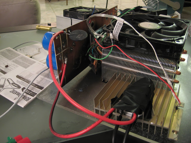
well, crap!
Note to self - remove oscilloscope probe grounding wire if not using the isolation transformer!
I was testing my setup on my vehicle pack. It's pretty much done, ready to go. I figured out a way to do isolated voltage measurement, written the appropriate code, and had it working on the resistive load - would hold a voltage +/- a few tenths of a volt.
I wanted to look at the waveform on the real application, so lugged out my isolation transformer, wired everything up and turned it on. Everything looked good - held current constant under 3A even though the inductor had discontinuous current, above 3A entered continuous conduction and the waveform looked pretty clean. Cool.
My isolation transformer is small, so I can't draw much power. I unplugged it, turned off the scope, and plugged the charger up to the 240AC.
POP! Blinding sparks! Ugh... Maybe it's ok - I know the concept works and I think I have an idea for a better layout using plus247 sized devices that'll be smaller and more organized.
What looks like a shadow on the plexiglass is really black soot from the mosfet...
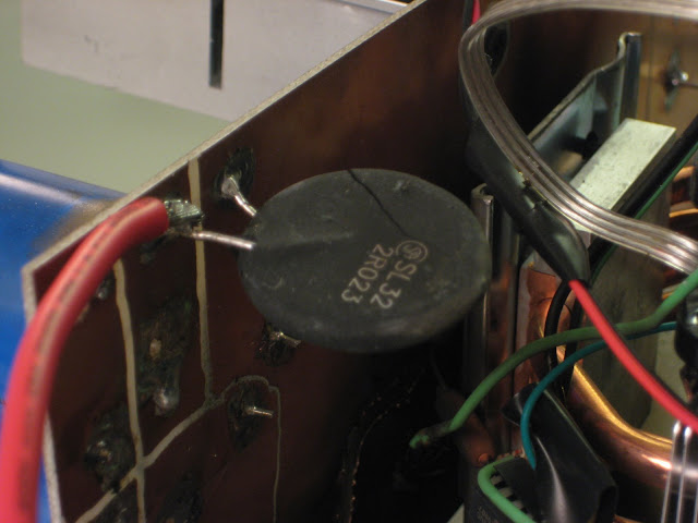
The inrush current limiter cracked...
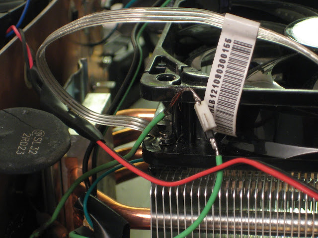
That grean wire is where the probe ground connected, Current flowed from the leads, through the board, through this green wire and to ground via the probe ground. Notice it's a little melted...
More blackness. The copper seemed to vaporize a little along one of the lines I milled.
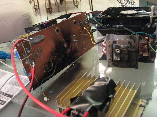
The vaporized copper is more visible... I think that the mosfet and current limiter are the only casualties, but I don't think I'd reuse the board only because I have a new layout planned.
 |
|
|
|
|
08-28-2009, 07:31 PM
|
#157 (permalink)
|
|
Joe
Join Date: Feb 2009
Location: phx
Posts: 260
Thanks: 0
Thanked 48 Times in 38 Posts
|
Quote:
Originally Posted by NiHaoMike
How about have the switching regulator operate as both a PFC and a charger?
|
From what I understand, in order for the load to appear resistive at the input while the output current is constant, the input and output need to be decoupled. Hence, one stage to create a 'resistive' load and another stage to output constant current with a capacitor in between.
Arguably, the output current does not necessarily need to be constant for a lead acid battery charger, so I'm sure it can be done. In fact, there are many ways to solve the battery-charger problem, from a handful of extension cords and a rectifier to a full blown PFC stage/buck mode charger, or maybe some other super complicated method. Each has its advantages and disadvantages.
So far, despite the recent setbacks, I've enjoyed the challenge of a micro controlled buck mode charger and think it'll provide the best combination of performance in terms of power, efficiency, flexibility, and battery care. If PF is too low, that's another fun problem to solve. But, by no means do I suggest it's the best solution for everyone... |
|
|
|
|
09-17-2009, 01:48 AM
|
#158 (permalink)
|
|
EcoModding Lurker
Join Date: Jul 2009
Location: Seattle
Posts: 18
Thanks: 0
Thanked 1 Time in 1 Post
|
Any more progress to report? I'm looking forward to firing up my soldering iron, but don't know enough to do R&D.
|
|
|
|
|
09-17-2009, 02:46 PM
|
#159 (permalink)
|
|
Needz Moar Jiggawatts
Join Date: Sep 2008
Location: Canada
Posts: 30
Thanks: 5
Thanked 3 Times in 3 Posts
|
Quote:
Originally Posted by NiHaoMike
The peak voltage for 120v AC is right about the correct charge voltage for a 144v lead acid pack! In fact, I remember reading about someone who made a large UPS with little more than 12 12v batteries and a bridge rectifier.
|
I don't think that's correct. The bridge rectifier shouldn't put out the peak voltage of the ac sine wave; it should put out the *average* voltage minus Vf of the diodes (0.637*Vpk -1.4). Feel free to correct me if I'm wrong.
The old K&W BC-20 I have a passing familiarity with was incapable of charging above 108V packs from the standard ac line. It required a Line Booster to charge 120V packs.
__________________
In theory, theory and practice are the same. In practice, they aren't.
|
|
|
|
|
09-17-2009, 02:56 PM
|
#160 (permalink)
|
|
EcoModding Lurker
Join Date: Jul 2009
Location: Seattle
Posts: 18
Thanks: 0
Thanked 1 Time in 1 Post
|
I might also be wrong, but it's my understanding that after the bridge rectifier there is normally a filter capacitor which maintains the output voltage very near peak.
|
|
|
|
|
The Following User Says Thank You to vwdevotee For This Useful Post:
|
|
|