 07-21-2009, 01:18 PM
|
#1 (permalink)
|
|
Joe
Join Date: Feb 2009
Location: phx
Posts: 260
Thanks: 0
Thanked 48 Times in 38 Posts
|
Revolt Open Source DC Controller Beta Testing
I started this thread to hold all the testing details and results that's going on down here in AZ. One location should make it easier to find stuff if someone is curious about past details or whatever.
My car basics:
1989 Toyota Corolla
24x 6v US2200 GC flooded batteries
Impulse 9 (warp)
3750 lb
clutchless
Curtis 1231c (originally)

The car is an elephant in disguise. Most people are amazed at the 7 batteries under the hood and then are really surprised to find 17 more in the trunk. I built it for my longest commute of a 52mi round trip to the west side of town and back.
The impulse 9 has a lower torque curve than the warp 9, so i think it behaves more like an 8" motor. Starting in 1st gear gives decent acceleration while 2nd gear is pretty slow to get goin.
The Curtis did an adequate job of powering this beast. the whine was annoying and it would often go into current limit mode now that we're into summer. I have a thermal probe in a hole in the heatsink. it's filled with thermal paste near the bottom of the controller - it's pretty good i think, I could see a rise and fall in temp when pulsing the throttle. In the recent hot weather, I saw it get up to 55C in driving around town. Freeway driving is actually less demanding.
More info about the car:
EValbum: Joseph Yanof's 1989 Toyota Corolla
Photos: Picasa Web Albums - Joseph - ecar Album
|
|
|

|
 Today Today
|
|
|
|
 Other popular topics in this forum...
|
|
|
|
|
07-21-2009, 01:21 PM
|
#2 (permalink)
|
|
Joe
Join Date: Feb 2009
Location: phx
Posts: 260
Thanks: 0
Thanked 48 Times in 38 Posts
|
I just copied this from the other thread:
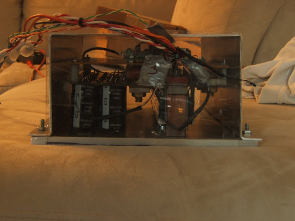
it works! It took a while to install, but I accomplished a bunch of stuff. I had to move the heatsink out aways to make room for the mounting flanges and while I had everything apart, I tinned the bus bars. I also put together a simple 4 probe temperature gauge. it uses an atmega16 that i had laying around and 4 thermistors and just scrolls through the temperature readings on an LED display.
This shows the rear of the controller with 3 of the 4 probes in the controller. I had one taped to a capacitor, another wedged in between the space above a mosfet, and another wedged in between the space above a diode. I used folded up paper to wedge it in there so that the thermistor was pressed against the top of the mosfet/diode case.
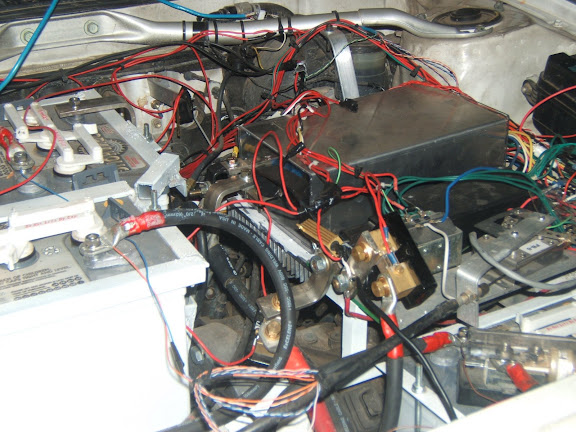
Installed in the car amongst the web of wires...
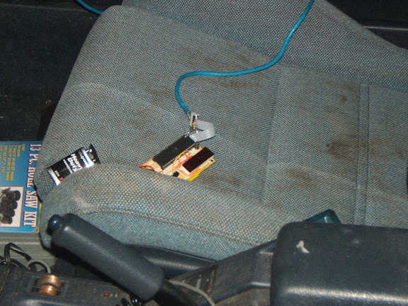
The temp probe circuit and display just sits in the front seat for now...
The coolest thing for me has to be the silence when moving slow... I'm too used to the curtis and its squeal!
Paul, I noticed the 'bucking bronco' phenomenon that I think you mentioned before. I'd guess that the control loop is acting too fast and gets into an oscillation - it sounds like you have it worked out, so i'm anxious to try out the new loops.
The accelerator position = torque thing is quite different. I'm used to having to press the pedal ever so slightly and then press further and further to go faster and faster. Now, it's almost the opposite! I have to press the pedal deeply and then release it as the car accelerates.
I only took a few trips around the neighborhood (got a little late), but i did get a little bit of temperature data. Ambient temp = 34C. I did 8-10 accelerations to 25 mph pulling 200-400 amps each and I noticed the mosfet and diode temp get up to about 60C while the cap temp seemed to stay lower in the low 40's (don't remember). I want to double check the accuracy of my probes, but I think they're pretty good.
More testing to come! |
|
|
|
|
07-21-2009, 04:39 PM
|
#3 (permalink)
|
|
PaulH
Join Date: Feb 2008
Location: Maricopa, AZ (sort of. Actually outside of town)
Posts: 3,832
Thanks: 1,362
Thanked 1,202 Times in 765 Posts
|
Hey Joe! Do you have the 6 ISP wires accessible even with the enclosure on? I think my 6.7" diameter motor behaves pretty different from your 9" motor. It seems to me that something that feels smooth to me feels pretty jerky to you. I think your motor is lower inductance.
I think it's going to take several variations on the throttle to get it to what feels good to you. It would be nice if the ISP wires were already out with the other wires, so you could just hook up your laptop (and stk500) and program the chip without taking off the case each time.
I'm not sure if a tuned loop for me will behave the same for you. I'll send you code for the PI version with a conservative throttle ramp. I may be using too large of P and I values for your motor, though, but we can try it and see what happens. If it is still jerky or oscillating, I'll know to make the P and I smaller. I'll also send you just a basic ramping code program, that takes both pwmDuty AND current into account, so it might feel more similar to the Curtis. Also, I'll make sure the overtemp is set to about 75 degC to start.
One reason it might feel like you have to push a lot on the gas to get going is that I have a pretty conservative dead zone for the throttle. Maybe it's too big? I just didn't want to risk having the car take off because the pedal was SLIGHTLY above 0 throttle.
|
|
|
|
|
07-21-2009, 05:52 PM
|
#4 (permalink)
|
|
Joe
Join Date: Feb 2009
Location: phx
Posts: 260
Thanks: 0
Thanked 48 Times in 38 Posts
|
I don't have the wires easily accessible at the moment, but that should be easy to arrange. It's not always jerky, just sometimes at the right pedal input. going up the driveway was particularly jerky.
With regards to the deep pressing pedal, I think it's just because my setup requires a lot of amps to get going (combination of lotsa weight and goin with the impulse 9 motor). For example, when I started off in 2nd gear with the curtis, I'd peg the output at 500A for 5 seconds or so before the car got going enough that the current dropped. While that was just a small pedal depression before, that'd require flooring it now. It's just different...
How does this other throttle thing work?
|
|
|
|
|
07-21-2009, 06:03 PM
|
#5 (permalink)
|
|
PaulH
Join Date: Feb 2008
Location: Maricopa, AZ (sort of. Actually outside of town)
Posts: 3,832
Thanks: 1,362
Thanked 1,202 Times in 765 Posts
|
The one you have right now is a current ramping code I believe. Increment current . It's not a PI loop. It sounds like at low RPM, the current was swinging back and forth. A properly tuned PI loop should be much better, but it might take a few tries to find the right P and I for your motor. I'm certain it would be different from mine. Probably smaller P and I values, but I don't know how much smaller.
The third option looks a little like this:
if (pwmDuty > throttlePos) {
pwmDuty--;
}
else if (current > throttlePos) {
pwmDuty--;
}
else if (pwmDuty < throttlePos) {
pwmDuty++;
}
So, you don't get the jerky starts from throttle only being proportional to pwmDuty, since current can't be bigger than throttle either.
|
|
|
|
|
07-21-2009, 06:44 PM
|
#6 (permalink)
|
|
Joe
Join Date: Feb 2009
Location: phx
Posts: 260
Thanks: 0
Thanked 48 Times in 38 Posts
|
Interesting! I'd definitely like to try some sort of PI loop - just curious, why no derivative term?
I like the third option too - It sounds like a way to have control of current at low speeds; i'd probably set it up for half the pedal range or something. Maybe this middle term would be:
else if (current/2 > throttlePos) {
pwmDuty--;
}
with 144V input and the Curtis, I'd rarely press the pedal more than 65% or so, meaning that my max required duty cycle is about .65. I'd cruise around 50%, and hill climb at 65%. (i'm basing these numbers off of the ratio of battery amps to motor amps). Occasionally, I'd punch it to merge or something, but that is rare.
I really like the idea of the PI loop to control current though - seems like it would truly make the hardware overcurrent feature more of a a protection feature than an integral part of the controller operation. I'm toying in my mind how to integrate the two... haven't figured it out yet.
|
|
|
|
|
07-21-2009, 07:12 PM
|
#7 (permalink)
|
|
PaulH
Join Date: Feb 2008
Location: Maricopa, AZ (sort of. Actually outside of town)
Posts: 3,832
Thanks: 1,362
Thanked 1,202 Times in 765 Posts
|
I just took a drive with a PI loop that is pretty well tuned to my motor. However, with the added feature that throttle doesn't change instantly, but rather has a max ramp rate. So, let's say you floor it. The slowThrottle will be heading toward actualThrottle, and the PI loop will be making sure the current is exactly matching the slowThrottle on it's journey. It felt really good in my car, but that doesn't mean anything. hehe. If you feel oscillations or jerkiness, I'll decrease my P value some and we can try it again.
I didn't include a derivative term because the EVTech people suggested to me that it is more likely to cause instability in this context. I read up on it, and each control loop I read about for high power motor controllers didn't include the derivative part. Based on the graphs I've gotten from my serial port, it seems that the current converges to the throttle exponentially, so I think it's OK with just P and I.
I was thinking about how to integrate the 2 also! Lots of fun stuff to try!
I'll email you the PI version with P = 18 and I = 150 (meaning 18/32, 150/32000). If it's too jerky, I'll send you one with P = 10 or something like that. Or you can just change Kp in the program to whatever you want! hahaha! It's just a variable. I keep forgetting you have an STK500. As an example, changing Kp to 10 in the program would be the same as changing it's actual value to 10/32.
Last edited by MPaulHolmes; 07-21-2009 at 08:34 PM..
Reason: typo
|
|
|
|
|
07-21-2009, 08:19 PM
|
#8 (permalink)
|
|
Joe
Join Date: Feb 2009
Location: phx
Posts: 260
Thanks: 0
Thanked 48 Times in 38 Posts
|
sweet! I'll give that a try.
I tried to come up with something that integrates the throttle to PWM and a PI loop and couldn't do it. Only thing I could come up with was using a PI loop in the 2nd term if current>pwmDuty.
Here's another idea - maybe kinda hairbrained. what if the the throttle didn't control PWMduty or current, but controlled output power. PWMduty is proportional to output voltage, we're measuring current, so the product of those two would be power (or something proportional to power).
I have no idea if this would work, i haven't thought through the details. well, i'm sure we can get it to work, but i don't know how it'd result in 'feel'.
think about it...
|
|
|
|
|
07-21-2009, 09:53 PM
|
#9 (permalink)
|
|
PaulH
Join Date: Feb 2008
Location: Maricopa, AZ (sort of. Actually outside of town)
Posts: 3,832
Thanks: 1,362
Thanked 1,202 Times in 765 Posts
|
I just got it working with throttle proportional to power! Very nice feel! It's different from both of the others (to current or to pwmDuty). It really feels like a hybrid of the 2. My ramping is a bit too slow, but I'll take care of that. It feels really nice! That was a really really good idea you had! I'll email it to you later. My son just woke up. Great idea, Joe!
EDIT: Actually, I can also try a PI loop on this so as to make power converge to throttlePos exponentially.
Last edited by MPaulHolmes; 07-21-2009 at 11:30 PM..
|
|
|
|
|
07-22-2009, 12:55 AM
|
#10 (permalink)
|
|
Joe
Join Date: Feb 2009
Location: phx
Posts: 260
Thanks: 0
Thanked 48 Times in 38 Posts
|
Quote:
Originally Posted by MPaulHolmes

EDIT: Actually, I can also try a PI loop on this so as to make power converge to throttlePos exponentially.
|
Awesome! That's exactly what I was thinking.
|
|
|
|
|


