Branched off from this (old) thread here:
http://ecomodder.com/forum/showthrea...-vx-14029.html
Thought it might be helpful to some Honda VX owners. I can only validate that the wiring works for a 1994 California-specific Honda VX (though I do have the Fed ECU in it right now).
Some helpful pinout information is here:
.:FFS TechNet : OBD1 ECU Pin out Schematics :.
Hopefully these pics will help a bit too.
Disclaimer: I prefer reversible mods in general, which applies to electrical mods too. I particularly dislike those "splicing" clips which cut into the electric wires when clamped shut; I've had enough occurrences of those wearing through the wires completely over time that I refuse to use them anymore. And if I don't have to cut and solder, I won't. This approach may not be for you, but that's what I'm showing here.
First, ECU connections. I made the connections I needed for the 'guino directly at the ECU connector.
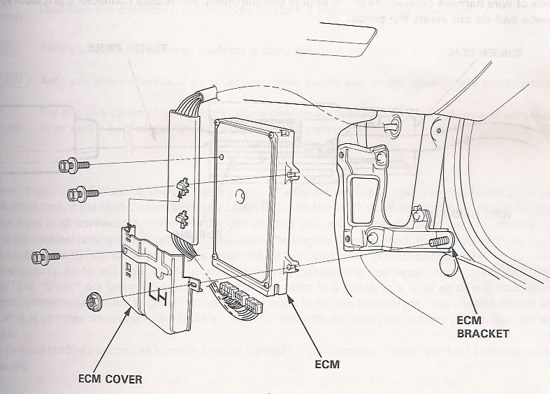
The ECU is to the right of the passenger footwell (assuming LHD of course). A bit of a bugger to get out so that I could get at the connectors, but it's doable. Service manual pics help:
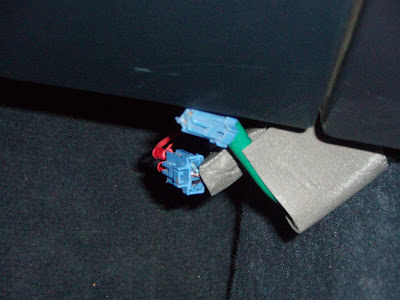
After getting the connectors off, it's not too tough to figure out which connections you need, based on the images and wire colors given by the reference you linked to above. Each of the three connectors is a distinct size. For example, the VSS signal is included in the "B" connector, which is the smallest of the three. The VSS signal is at pin 10, and should be either yellow with a blue stripe or orange. In my case, it was yellow with a blue stripe (see arrow):
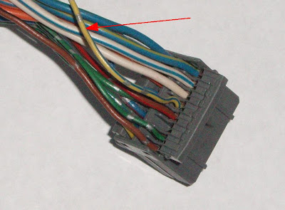
BTW - I had a spare harness, which I used to get these pics rather than dissassembling my footwell again... hope you understand...

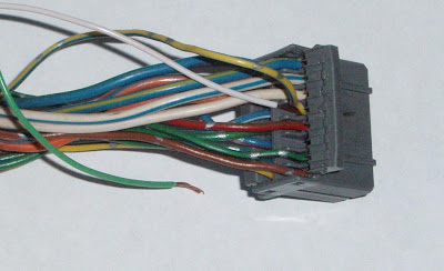
You might notice in the pic above that there is an open hinged 'cover' over the ends of the wires... I take advantage of the cover when I 'connect' my wires.
With 22gauge speaker wire, I can strip the ends, bend a little 'nub' into the exposed wire, and then shove it in with the needed connector slot (VSS in this case) (see the white wire in with the yellow with blue stripe wire):
Then I can snap the 'cover' back in place which helps hold my wire in place:
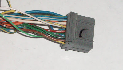
I also used electrical tape to keep the added wire from pulling out any.
I'll leave the Injector Pulse connection as an exercise for the reader. You can use any one of the 4 injector signal wires, which are on connector 'A', pins 1, 2, 3 or 5. You only need one.
Next, constant power. There is a 3-pin Data Link Connector also on the right side of the passenger footwell, just under the glove box. There are two connectors under there; one is the 3-pin connector and the other is a 2-pin Service Check Connector. Service manual image gives you an idea of where it's at (ignore the text about the jumper wire; it's unrelated to this topic. It's the best pic I could find in the service manual that shows where this Data Link Connector is located):

And here's a pic of it in my car:
The connectors are hidden behind the panel normally. The two outside pins of the 3-pin connector are always live; black is ground and blue is +12v. They are protected by a 7.5Amp fuse ( I think it is ) which should be plenty for the 'guino. My connectors are a bit hokey; next time I hit the wrecking yard, I'll see if I can find a standard connector that fits the 3-pin so it looks a bit cleaner.
Let me know if you have any questions...