09-25-2021, 01:22 PM
|
#31 (permalink)
|
|
EcoModding Lurker
Join Date: Jan 2021
Location: Ontario, Canada
Posts: 68
Thanks: 54
Thanked 50 Times in 35 Posts
|
Thanks, Aerohead! I didn't see indication of a roof camber to be included into aft-body ration in the SAE 810185 but now when you mentioned, it makes sense.
Without roof camber :
* L0 / L -ratio of 0.3441 (without a tail extension)
* L0 / L of 0.4087 (with the tail extension)
With roof camber:
* L0 / L -ratio of 0.5234 (without the tail extension)
* L0 / L of 0.5704 (with the tail extension)
According the SAE 810185, it implies that larger aft-body ratios has chance achieving lower drag coefficients.
I have a sideview profile of the truck roof (from the windshield to the rear window) which then continues to the end of the bed and beyond. The roof peak seemed to be fairly front of the cabin (towards windshield) which increases the aft-body ratios. I have a cardboard template from the top of the windshield all the way down to the end of the bed and beyond where I fitted the sideview profile.
|
|
|

|
|
The Following User Says Thank You to tomi_k For This Useful Post:
|
|
 Today Today
|
|
|
|
 Other popular topics in this forum...
|
|
|
|
|
09-25-2021, 02:40 PM
|
#32 (permalink)
|
|
EcoModding Lurker
Join Date: Jan 2021
Location: Ontario, Canada
Posts: 68
Thanks: 54
Thanked 50 Times in 35 Posts
|
An attempt to questimate what happens DeltaCd (min.) vs. slope angle (at min DeltaCd). with aft-body -ratio beyond of 0.45....
|
|
|
|
|
The Following User Says Thank You to tomi_k For This Useful Post:
|
|
|
09-29-2021, 10:48 AM
|
#33 (permalink)
|
|
Master EcoModder
Join Date: Jan 2008
Location: Sanger,Texas,U.S.A.
Posts: 16,534
Thanks: 24,520
Thanked 7,438 Times in 4,818 Posts
|
aft-body ratio
Quote:
Originally Posted by tomi_k

An attempt to questimate what happens DeltaCd (min.) vs. slope angle (at min DeltaCd). with aft-body -ratio beyond of 0.45....
|
A few numbers we have for pickups is for Brett Herndon's Aerolid, for the Ford F-150 pickup. Ford Motor Company was so impressed with Brett's aeroshell that they paid for the wind tunnel testing.
Brett's Aerolid measured a delta-Cd= 0.067 reduction.
Brett's boat tail was good for delta-Cd 0.031 drag reduction.
With both, Aerostealth, who bought one of each, was able to achieve Cybertruck's drag coefficient in 2014.
In Feysal Ahmed's Master's Thesis, he was able to see a delta- 19% Cd with his 3-D type aeroshell.
From the two trips to the wind tunnel with the T-100, with the 'cleanest' configuration, and allowing for the blockage ratio comparison model, there's a strong probability that the truck measured as low as Cd 0.17 ( as a 'camera' truck ), if measured at the A2 Wind Tunnel ( which I hope to validate when I go there ).
Whatever you do, you're not going to see any truly remarkable drag reduction until you put some boat-tailing on the truck. The virtually 'slab-sides' of pickup beds preclude any meaningful pressure recovery along the sides, relying solely on the 'roof' for all the heavy lifting. 
__________________
Photobucket album: http://s1271.photobucket.com/albums/jj622/aerohead2/
|
|
|
|
|
The Following 2 Users Say Thank You to aerohead For This Useful Post:
|
|
|
10-15-2021, 11:03 AM
|
#34 (permalink)
|
|
Master EcoModder
Join Date: Jan 2008
Location: Sanger,Texas,U.S.A.
Posts: 16,534
Thanks: 24,520
Thanked 7,438 Times in 4,818 Posts
|
' Re: your second picture'
Quote:
Originally Posted by Vman455
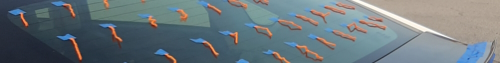
Re: your second picture--
Pressure always acts normal to a surface. The arrows in the lower image are not correct.
A spoiler affects flow upstream because pressure is transmitted through air (fluid) at ~340 m/s. Fitting a spoiler may increase pressure as far upstream as the roof, as I found on my Prius with a small lip spoiler:
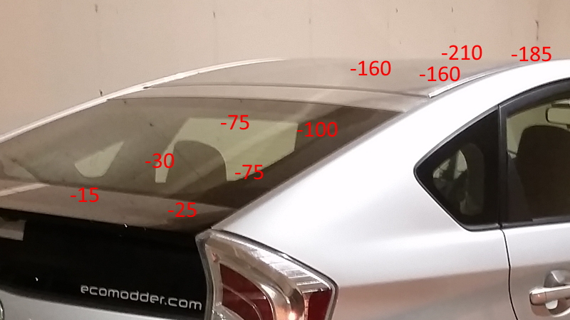 Gauge pressures with no lip spoiler
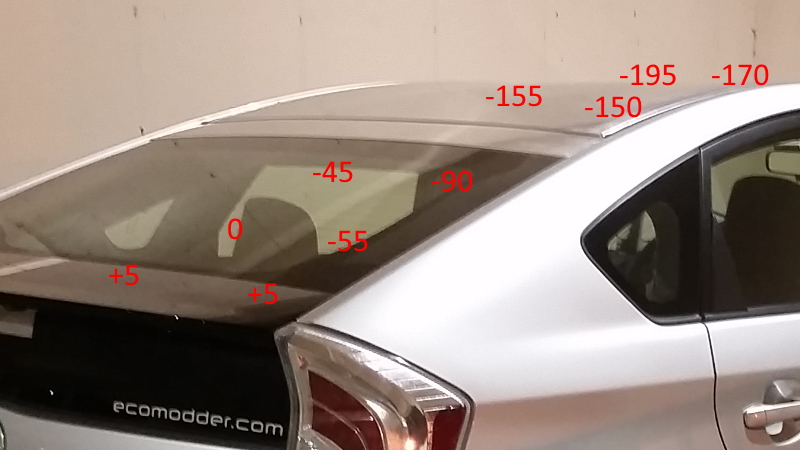 Gauge pressures with lip spoiler
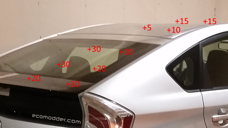 Difference
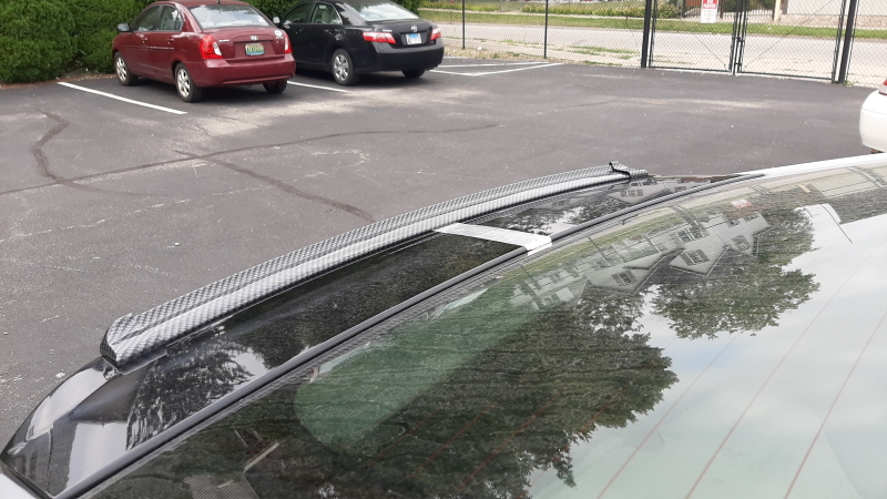 Lip spoiler for reference
Les than $100 worth of equipment and a couple hours and you can measure yourself and find out what a spoiler does on your car. |
Sorry, I couldn't figure out which picture you're referring to. None of my images have 'arrows.'
__________________
Photobucket album: http://s1271.photobucket.com/albums/jj622/aerohead2/
|
|
|
|
|
The Following User Says Thank You to aerohead For This Useful Post:
|
|
|
10-16-2021, 09:18 AM
|
#35 (permalink)
|
|
Moderator
Join Date: Feb 2012
Location: Urbana, IL
Posts: 1,940
Thanks: 199
Thanked 1,807 Times in 943 Posts
|
I was referring to this image:
 |
|
|
|
|
The Following User Says Thank You to Vman455 For This Useful Post:
|
|
|
10-20-2021, 11:21 AM
|
#36 (permalink)
|
|
Master EcoModder
Join Date: Jan 2008
Location: Sanger,Texas,U.S.A.
Posts: 16,534
Thanks: 24,520
Thanked 7,438 Times in 4,818 Posts
|
image
Quote:
Originally Posted by Vman455
I was referring to this image:
|
Thanks, I've never seen that one. Do you know who posted it?
-------------------------------------------------------------------------------------
Ah, never mind, I just found it at #19 permalink! I never clicked on the second image, and missed the red arrows you were referring to. Oh the difference a mouse-click will make!
__________________
Photobucket album: http://s1271.photobucket.com/albums/jj622/aerohead2/
Last edited by aerohead; 10-20-2021 at 02:31 PM..
Reason: correct citation
|
|
|
|
|
The Following User Says Thank You to aerohead For This Useful Post:
|
|
|
10-20-2021, 03:05 PM
|
#37 (permalink)
|
|
Master EcoModder
Join Date: Jan 2008
Location: Sanger,Texas,U.S.A.
Posts: 16,534
Thanks: 24,520
Thanked 7,438 Times in 4,818 Posts
|
if flow is attached
Quote:
Originally Posted by tomi_k
Thanks, Aerohead & Freebeard ! Just trying to get my head around the topic what matters the most... and learning. And thanks for being patient to respond (probably basic and silly questions) but gotta start from somewhere....
<Quote>
* Flow reattaches on top of the spoiler, and captures a locked-vortex against the body, as high as the spoiler.
</Quote>
From drag perspective, the air flow before the spoiler what happens for the overall drag if
a) flow on front of the spoiler is attached? If flow is attached, is the spoiler directed air flow direction reducing the drag (i.e. surface pressure direction (at the end) -> without spoiler the surface pressure is against the direction of vehicle movement vs. with spoiler the surface pressure is in same direction of vehicle movement)?
b) flow on front of the spoiler is not attached -> and creates a "air bubble" (turbulent)... is this what causes overall drag increase if wake increase is not necessary the dominant factor?
According one of Hucho's document (see picture attached), if I understood correctly, regardless of attached or separated airflow, when the critical angle of rear portion of the shape is exceeded, overall drag will increase. Unfortunately, I found this information a bit too late but glad I found it.
The other attached picture is an illustration of what I am trying to understand... If Hucho's document info is correct and valid... is there a way to recover "penalty of overall drag" caused by exceeded rear slanted angle as it sounds like increased drag is evident regardless what type of flow over the rear shape one has and/or and if wake area is reduced?
|
1) since the template is streamlined, the flow would be fully attached.
2) flow would be increasingly decelerating over the length of the entire roof, aft of the roof apex.
3) local static pressure would be increasingly rising, in proportion to the local velocity, as the flow moved rearwards.
4) when flow reached the end of the body and detached, it would be the 'slowest' and 'highest' pressure, having recovered pressure the entire length of the roof.
5) there would be no separated wake, just a thick turbulent boundary layer sloughing off the body.
-------------------------------------------------------------------------------------
6) the addition of a rear spoiler would introduce an obstacle in the flow path, requiring the flow to re-accelerate to a higher velocity around the larger cross-section, and at lower local static pressure.
7) the local separation line would move to the periphery of the spoiler.
8) a turbulent wake would be introduced.
9) direct downforce would be introduced.
10) at the expense of lower base pressure
11) higher pressure drag.
12) higher overall drag.
__________________
Photobucket album: http://s1271.photobucket.com/albums/jj622/aerohead2/
|
|
|
|
|
The Following User Says Thank You to aerohead For This Useful Post:
|
|
|
10-20-2021, 05:33 PM
|
#38 (permalink)
|
|
Master EcoModder
Join Date: Jan 2008
Location: Sanger,Texas,U.S.A.
Posts: 16,534
Thanks: 24,520
Thanked 7,438 Times in 4,818 Posts
|
drag penalty comparison ( sort of )
I dredged up a couple of cars which share similar curved-roof length percentages.
The Ford / Merkur-Scorpio 2-door, and VW 2000.
Both have around 38% aft-body, Cd 0.33, and Cd 0.25, respectively.
--------------------------------------------------------------------------------------
*The Ford starts with a 25-degree fastback ( as measured from the horizontal ).
* The 'notchback' shelf / step is added, relaxing the rear slope to 19.5-degrees.
* A lower rear spoiler is added, increasing height and length, relaxing the slope angle further, to 16.4-degrees.
* Finally, the upper wing is added, creating a 14-degree slope angle off the backlight within an inch of the 'fast' template, and Cd 0.33.
--------------------------------------------------------------------------------------
* Volkswagen just goes for the throat, with a simple non-porous fastback, of 14-degrees downslope angle, with a perfect match to Wolfgang Klemperer's Cd 0.15 Basic Body contour of 1922, coming in at Cd 0.25, 70.4 - inches ( 1,788mm) short of Klemperer's long-tail total length.
-------------------------------------------------------------------------------------
* Klemperer's tail reaches a maximum rear slope angle of 24.5-degrees, exceeding Mair's recommended 22-degrees at 89% tail length.
This appears to be the same contour Toyota has chosen for all their Prius variants, since the Gen-II. Which, on the Prius, also happens to match Mair's transition region to 22-degrees rear slope.
__________________
Photobucket album: http://s1271.photobucket.com/albums/jj622/aerohead2/
Last edited by aerohead; 10-20-2021 at 05:39 PM..
Reason: add data
|
|
|
|
|
The Following User Says Thank You to aerohead For This Useful Post:
|
|
|
10-20-2021, 08:26 PM
|
#39 (permalink)
|
|
EcoModding Lurker
Join Date: Jan 2021
Location: Ontario, Canada
Posts: 68
Thanks: 54
Thanked 50 Times in 35 Posts
|
Aerohead : I guess you figured out that I posted those pictures with the arrows which also had a mistake regarding the arrows not pointing perpendicular to the roof line, apologies for that.
I just did it quickly to try to simplify my questions what I tried to figure out regarding what happens at the end with a spoiler, how spoiler acts in terms of drag, how overall airflow "sees" the spoiler and what is impact of that to overall drag vs. the roof angles.
Thanks for detailed responses on this matter - much appreciated.
Last edited by tomi_k; 10-20-2021 at 09:48 PM..
|
|
|
|
|
The Following User Says Thank You to tomi_k For This Useful Post:
|
|
|
10-20-2021, 10:51 PM
|
#40 (permalink)
|
|
Master EcoModder
Join Date: Aug 2012
Location: northwest of normal
Posts: 29,418
Thanks: 8,368
Thanked 9,128 Times in 7,537 Posts
|
When the target is 22 degrees, in plan that's 44 degrees --close enough to 45.
In my experiment with Zeppelin-izing a Beetle I established a 45 degree bulkhead and found where the gentlest curve to reach it was.

The solid bulkhead is where a boat tail without the reflex curve would terminate. The open bulkhead is at the original bumper location. I think terminating in a vertical line instead of a low point would impart directional stability.
I guess I've never posted the picture, but I established that a Studebaker Starlight-style V-shaped window would not impair rear vision. Cooling would be through the front of the rear fenders. Oversize like Tatra to allow either side to work in a crosswind.
__________________
.
.Without freedom of speech we wouldn't know who all the idiots are. -- anonymous poster
___________________
.
.tragectory: Line goes down and to the right.
|
|
|
|
|
The Following User Says Thank You to freebeard For This Useful Post:
|
|
|