Mirrored at Instructables

In order to reduce the power consumption of the lighting system of my electric vehicle, I took it upon myself to change all of the lighting to LEDs. When it came to replacing the incandescent 18 watt 310 lumen headlight bulb, none of the drop-in LED replacement bulbs looked good to me. And none of them offered output levels that were comparable to or better than the bulb I was trying to replace.
So, I shopped around and decided to make my own. The approach I took was probably more complicated than what most of you will actually need, but since I put both available options in one headlight I can explain how to implement both.
DISCLAIMER
This guide assumes you will be using an input voltage between 12 and 14 volts. If you are using a different input voltage or LEDs of different ratings than what is indicated in this write-up you should use an LED Calculator to determine what resistors you need to use.
I would recommend this LED calculator:
LED Resistor Calculator
Part 1: LED Array Running Light
This option will be the most cost effective and easiest to assemble with basic tools. It's adaptable to whatever size, shape, or style of headlight you decide upon and if needed you can tailor the output level and pattern as well.
To calculate the potential output of the array you are going to make take the rating of the LEDs (6000mcd = 6 candela = 6 lumens) then multiply by the number of LEDs you intend to use.
I used 20 of the 6 lumen LEDs, so 20 x 6 means my output is approximately 120 lumens.
If you want more intensity it's best to start by using LEDs of a higher rating. Also keep in mind that even 6,000mcd LEDs will be painful to look at directly in the dark and will need to be diffused somewhat.
You can diffuse LEDs
1. by sanding their lenses with 600 grit sand paper
2. by making a soft diffusor sheet out of 1/16th or 1/8th inch clear or tinted acrylic or polycarbonate and then sanding it with 600 grit sand paper
3. by making a heavy diffusor plate out of 1/16th or 1/8th inch thickness white polyethylene sheet
Part 1 Supplies
1. Headlight fixture
2. Thin Polycarbonate or other suitable plastic sheet
3. Bulk lot of 50 to 100 white LEDs in 6000mcd or higher
You can order these cheaply from
Chi-Wing LED product shop
4. Resistors (180ohm 1/4w for 13.4v max input or 220ohm 1/4w for 14v max input)
5. 22ga Wire
6. Pack of full sheet label paper
Part 1 Tools
1. 45w+ Soldering iron
2. Wire cutters
3. Power drill
4. Tin snips, band saw, or scroll saw (tool for cutting thin plastic)
5. Super glue
6. Hot Glue (optional)
7. Scissors
Part 1: Step 1
Disassemble your fixture and measure the parts.

You will either be trying to mount your LED array off of the original reflector plate, or by replacing the glass lens with a plastic sheet that you can mount it on.
Part 1: Step 2
Use the dimensions taken to draw a CAD template of the array plate.

Any CAD software will do. If you do not have any CAD software I would recommend getting a free trial copy of
Alibre Xpress.
Draw the shape of the piece you want to make. Then add one hole the same size as the LEDs you intend to use. You can then duplicate that drilled hole in whatever pattern you want for however many LEDs you want. Just make sure to keep in mind that you will be wiring the LEDs in sets of 4, so the total number of holes will need to be a multiple of 4.
I went with a ring shape.
Part 1: Step 3
Highlight the finished sketch and then press the PrntScrn key

Past the image into any graphics program such as GIMP or Photoshop and then select only the yellow sketch lines and blue sketch nodes. Copy that part of the image and paste into a new image, then fill those colors with black.
Save that image as a .png file.
Part 1: Step 4
Place the image onto a page in Microsoft Word or Open Office. Format it's size on the page to match the size of the part in the CAD file.

Put one sheet of full sheet label paper face down into your printer and print out the page.

Use scissors to cut out the template, then apply it to the protective film/paper of the plastic sheet.
Part 1: Step 5
Drill the holes where indicated by the template, then cut the part to the shape indicated using tin snips, a band saw, or a scroll saw.

If you are making the part out of thin plastic such as 1/16th" thickness polycarbonate or ABS it will be very easy to cut with tin snips, so a power tool won't even be required. However a band saw or scroll saw will produce much cleaner edges and will allow you to cut more complex shapes.
Part 1: Step 6
Once the piece is made, test fit it in the fixture.

I wasn't complete happy with the look of the first piece I made nor did I like the lens that the fixture came with.
I ended up making a replacement out of gray PVC and the clear base disc from a CD-R spindle.
Part 1: Step 7
Place the LEDs into the array plate you made making sure that they are appropriately oriented with their leads bent to make series sets of 4 LEDs.

Solder the sets of 4 LEDs together. Solder a resistor onto the positive side of each set. I would recommend testing each set with a battery or variable power supply to confirm that you have them wired in the correct orientations. If on LED is wired in reverse orientation that particular set won't turn on.
Solder all of their negative leads together to make the Neg- input, then solder the leads of all of the resistors together to make the 12v+ input.
The wiring should match the following diagram.

Solder leads of wire onto the Neg- and 12v+ inputs. Mark the ends of the leads with tape or heatshrink.
Part 1: Step 8
Use a battery or variable power supply to test the fully wired array.
Once confirmed that it's wired correctly, use a dab of super glue or hot glue at the back of the LEDs to adhere them to the array plate.
Once the glue is dry, Assemble and test assemble the array into the fixture. Test again with the variable power supply or battery.

If super glue is used, make sure to take the fixture back apart and let the super glued parts dry out in the open for several hours. The fumes that super glue produces in the first 2 hours of drying will in enclosed spaces stick to and whiten fingerprints as well as fog up most clear plastics.
Part 1: Step 9
With the glue dried, do the final assembly.

If applicable, solder the connector onto the bare leads and you will have a completed LED array headlight.
Part 2: High Power LED "High Beam"
If you want even more intensity from your LED headlight you can add a High Power LED. These are available in outputs ranging from 100 to even 600 lumens! The LED I chose is a Luxeon Endor Rebel rated for 430 lumens at @ 7.5 watts.
You can order them
Cree LEDs - Led Driver - Led Fixtures - Led Optics - Luxeon LEDs - LED Supply.com which also stocks the optics for them if you want a certain output beam.
Part 2 Supplies
1. High Power LED
2. Lens (optional)
3. Small Heatsink
4. Resistor (8ohm 5w for 14v max input)
Part 2 Tools
1. 100w+ Soldering iron
2. Wire cutters
3. Power drill
4. Tapping bits (UNC #4-40 and whatever preferred size you want to use for mounting the heatsink to your fixture)
5. Super glue
6. Hot Glue (optional)
7. Scissors
Part 2: Step 1
I tore a heatsink off of an antiquated video card, sanded the base, then drilled and tapped holes for mounting the heatsink and retaining the LED onto the heatsink.

The LED and lens are held in place by the mounting screws.
Part 2: Step 2
Using a 100 watt or higher soldering iron, solder the 8ohm 5w resistor onto the positive pad of the LED, and a wire lead onto the negative pad.

The negative pad is thermally conductive onto the back of the LED PCB so you will need to keep it off of the heatsink when soldering. Because of the thermal transfer rate that results, a soldering iron rated lower than 100 watts is not likely to be able to keep the pad up to a high enough temperature to make a decent solder joint.
Once soldered, apply heatshrink to the connections. Then apply thermal past to the back of the LED and place it on the heatsink. Retain it by affixing the set screws to the heatsink.
Part 2: Step 3
Assemble the light unit. If needed, secure the wires to the array plate using hot glue so that any tugging on the wires won't stress the solder joints.

These pictures show the unit before I added the polyethylene diffusor inbetween the lens and the light array. A diffusor is highly recommended because the focused output of a High Power LED is literally blinding.

Test the unit with a battery or variable power supply.
 Part 2: Step 4
Install the finished light unit into the fixture and if needed solder on the connector.

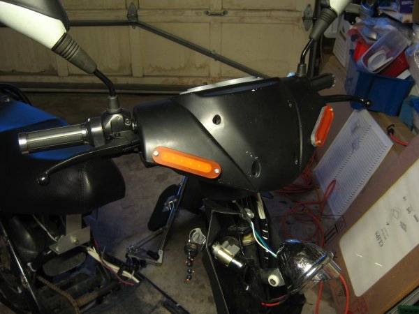
A comparison of the custom LED headlight and the headlight it is replacing.
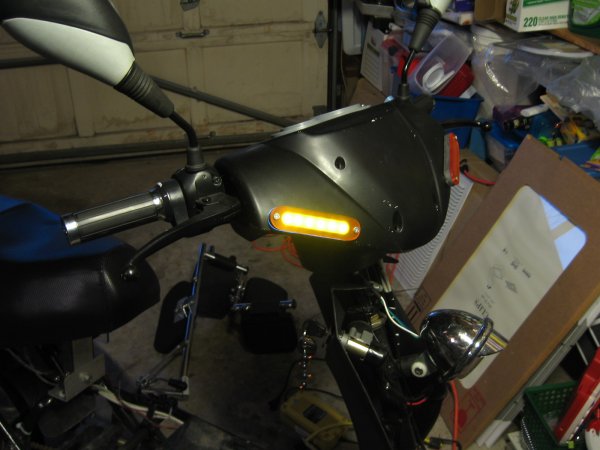
Comparison of the "running light" (Left) and "high beam" (right).
Part 2: Optional
If you add a capacitor to the circuit where appropriate, you can produce a fade affect when the headlight is switched from the "running light" to the "high beam".

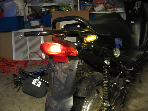
And that's it! LEDs allow you to make extremely long-lasting, highly efficient, vibration-proof, unique, and inexpensive headlights. The same process applies to making turn signals and brake lights.
However those won't require as high of an output level and most available drop-in replacements will work fine. But should you want something unique for those too, there's always the option to make your own.


 Today
Today