03-22-2011, 11:27 PM
|
#21 (permalink)
|
|
needs more cowbell
Join Date: Feb 2008
Location: ÿ
Posts: 5,038
Thanks: 158
Thanked 269 Times in 212 Posts
|
It was not a bad chip, it was bad process, conflicting mentalities (folks tend to peter out after the creative parts, leaving something of a mess), too much effort. Have fun. Please don't call it mpguino v2 though though because there is a "production" version that constantly gets confused in the discussions.
user: "My mpguino broke!"
me: "what is the problem"
user: "I tried a pic18f instead because it is a better chip"
me: "Doh!"
__________________
WINDMILLS DO NOT WORK THAT WAY!!!
Last edited by dcb; 03-22-2011 at 11:33 PM..
|
|
|

|
 Today Today
|
|
|
|
 Other popular topics in this forum...
|
|
|
|
|
03-22-2011, 11:56 PM
|
#22 (permalink)
|
|
EcoModding Lurker
Join Date: Sep 2010
Location: Fresno, CA
Posts: 78
Thanks: 4
Thanked 9 Times in 7 Posts
|
Quote:
Originally Posted by dcb

It was not a bad chip, it was bad process, conflicting mentalities (folks tend to peter out after the creative parts, leaving something of a mess), too much effort. Have fun. Please don't call it mpguino v2 though though because there is a "production" version that constantly gets confused in the discussions.
user: "My mpguino broke!"
me: "what is the problem"
user: "I tried a pic18f instead because it is a better chip"
me: "Doh!"
|
Understandable... sometimes you've just gotta smack a newb upside the head though. I've dealt with managing my own project (google FalconFour's Ultimate Boot CD), and dealing with user error has always been a fun one... it's pretty easy though when you realize that for every 1 user that's complaining about some obvious user error, there are also about a hundred other people silently enjoying your work every day and thanking you for it in their heads  Not saying I tell myself that or something (ooh, ego stroke! lol), just saying that's what I find for any small-group effort I find online. Just let the guy know they're working with an unsupported configuration, help the guy out if possible (e.g. "that's not supported, but duh, you plugged it in backwards"), and don't think too much of it! |
|
|
|
|
03-23-2011, 08:10 PM
|
#23 (permalink)
|
|
EcoModding Apprentice
Join Date: Jan 2010
Location: Newark, DE
Posts: 143
Thanks: 0
Thanked 14 Times in 14 Posts
|
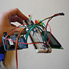
Mmmkay... Current hardware:
 |
|
|
|
|
03-23-2011, 09:43 PM
|
#24 (permalink)
|
|
Master EcoModder
Join Date: Feb 2011
Location: houston
Posts: 374
Thanks: 3
Thanked 38 Times in 33 Posts
|
well i like what it does just wish it expanded where I could have a tach on the screen too. and you guys make my head hurt reading this stuff.
|
|
|
|
|
03-29-2011, 03:34 PM
|
#25 (permalink)
|
|
EcoModding Lurker
Join Date: Mar 2010
Location: TN-USA
Posts: 61
Thanks: 0
Thanked 1 Time in 1 Post
|
I like the voltage buttons, this would free up 2 inputs  |
|
|
|
|
03-29-2011, 04:00 PM
|
#26 (permalink)
|
|
EcoModding Lurker
Join Date: Nov 2010
Location: S. E. Michigan
Posts: 45
Thanks: 0
Thanked 5 Times in 5 Posts
|
bobski
If your DX is stock DPFI your going to need to monitor both injectors. This of course would require using one interrupt per injector rather then the current arrangement of both interrupts to monitor one injector.
My thought on using one interrupt to capture an injector pulse is as follows. A pair of one shots are configured to trigger one on the rising edge and one on the falling edge of the injector pulse. The outputs of the two one shots feed an OR gate producing a signal that has a pulse on both edges of the injector pulse. This signal is feed to an interrupt input. The raw injector pulse is also fed into another digital input. The interrupt service routine is called for each rising and falling edge of the injector pulse and simply needs to check the state of the raw injector signal on the other input to determine what edge called the routine. This approach still requires two inputs to monitor an injector but only one interrupt per injector.
For the input zener diodes I would go with a lower voltage then 5.1 volts. Anything between 4.0 and 4.5 volts would be a better choice. The purpose of the zener is to limit the input voltage below the supply voltage so something less then 5.0 volts should be used. The input logic levels on the MCU are very low with anything over about 1.0 volts being recognized as high. A zener as low as 2.0 volts should work just fine but there is no need to go that low.
Mike
|
|
|
|
|
03-29-2011, 05:27 PM
|
#27 (permalink)
|
|
EcoModding Apprentice
Join Date: Jan 2010
Location: Newark, DE
Posts: 143
Thanks: 0
Thanked 14 Times in 14 Posts
|
Quote:
Originally Posted by msc
If your DX is stock DPFI your going to need to monitor both injectors.
|
It's not. Over the years, I've gone from stock DPFI D15B2 to a D16A6 with DPFI, to D16A6 with MPFI, to a D16Z6 with OBD-1 conversion.
Quote:
Originally Posted by msc
For the input zener diodes I would go with a lower voltage then 5.1 volts. Anything between 4.0 and 4.5 volts would be a better choice. The purpose of the zener is to limit the input voltage below the supply voltage so something less then 5.0 volts should be used.
|
Agreed, but in practice the voltage never hits 5.1 volts. When I bench tested the circuit with a 50K resistor and 5.1V zener, I could max out my power supply at 31-point-something volts and the voltage at the test point (the uP input in practice) only hit about 4.9V. I believe the rated voltage is at the diode's rated maximum current. I was using a pretty hefty zener current-wise, so the trickle of current through the 50K resistor at 12V was nowhere near that limit. |
|
|
|
|
03-29-2011, 05:30 PM
|
#28 (permalink)
|
|
EcoModding Apprentice
Join Date: Jan 2010
Location: Newark, DE
Posts: 143
Thanks: 0
Thanked 14 Times in 14 Posts
|
Quote:
Originally Posted by mcmancuso
I like the voltage buttons, this would free up 2 inputs |
I wish I could say it was my idea. ^_^ |
|
|
|
|
04-02-2011, 12:56 AM
|
#29 (permalink)
|
|
EcoModding Apprentice
Join Date: Jan 2010
Location: Newark, DE
Posts: 143
Thanks: 0
Thanked 14 Times in 14 Posts
|
Quote:
Originally Posted by msc
My thought on using one interrupt to capture an injector pulse is as follows. A pair of one shots are configured to trigger one on the rising edge and one on the falling edge of the injector pulse. The outputs of the two one shots feed an OR gate producing a signal that has a pulse on both edges of the injector pulse. This signal is feed to an interrupt input. The raw injector pulse is also fed into another digital input. The interrupt service routine is called for each rising and falling edge of the injector pulse and simply needs to check the state of the raw injector signal on the other input to determine what edge called the routine. This approach still requires two inputs to monitor an injector but only one interrupt per injector.
|
I wasn't quite following before, but I get what you're saying now. Use the interrupt as a "hey, something changed" input, then have the ISR check the various inputs to see which one it is. From there I guess it would take appropriate action, then set a variable or just a bit so it can figure out what's changed next time it's called.
For every injector (or other pulsed input) you would have a pair of one-shots outputting to that one interrupt line, and run the injector signal itself to a dedicated general purpose digital input so the ISR can check it. |
|
|
|
|
04-06-2011, 08:02 AM
|
#30 (permalink)
|
|
EcoModding Lurker
Join Date: Nov 2010
Location: S. E. Michigan
Posts: 45
Thanks: 0
Thanked 5 Times in 5 Posts
|
Yes, that's the concept. The ISR for the first injector would simply combine the current injector open and injector closed routines with a bit read and conditional statement that determines which routine to execute. I'm pretty sure it could look something like: IF (input bit) THEN (injector open routine) ELSE (injector close routine).
Of course this would be a pointless exercise that adds two chips unless the second interrupt is put to good use.
Since you are working on a general re-rendering of the concept you might try and add DPFI support. It would be a significant contribution and you would be a hero to a number of people with throttle body injection.
Adding support for a second injector would require a second set of injector calibration values and summing the output of both injectors for total fuel flow.
On another topic. If you want to really keep the inductive kick of the injector away from the MCU you can give the input side of the opto it's own ground wire back to near where you pick up the injector signal, presumably at the ECU.
Mike
|
|
|
|
|