 05-07-2020, 09:53 AM
|
#71 (permalink)
|
|
EcoModding Lurker
Join Date: Feb 2020
Location: North carolina
Posts: 45
Thanks: 6
Thanked 45 Times in 24 Posts
|
Awesome information! Just scrolled the all the possible obd pids and found the map psi and the vehicle load % pids. Set up a screen showing those, plus speed, rpm and throttle position command value and will experiment with it. Fingers crossed that there is a usable method to make the throttle stop testing method work. Will be over a week before I have results as am leaving in a couple days for a short trip in my old RV.
|
|
|

|
 Today Today
|
|
|
|
 Other popular topics in this forum...
|
|
|
|
|
05-07-2020, 05:53 PM
|
#72 (permalink)
|
|
Banned
Join Date: Nov 2017
Location: Australia
Posts: 2,060
Thanks: 107
Thanked 1,605 Times in 1,136 Posts
|
Quote:
Originally Posted by JulianEdgar

And now I have tested on a day with gusting 25-30 km/h crosswinds. And, in those conditions, the Edgarwits do absolutely nothing to reduce drag. The throttle-stop speeds with and without the aerofoils is identical.
So that behoves the question: do any air curtains work in gusty crosswinds? I have never seen any published research on this, so I have asked an expert I know. It will be interesting to see what he says.
|
The expert got back to me (he is head of aero at a major car company and had already given me feedback on the throttle-stop drag testing method).
I first asked him if the window up / window down results I was getting in different wind conditions were reasonable. He said:
Your window-opening results look plausible to me (not that theres much data around).
I then asked him about the Edgarwits air curtains not appearing to work in crosswinds. He said:
I like your air curtain. Id call it a turning vane, as its external. Looks similar in concept at least to something I experimented with a while back. I think your results are about right for that kind of system. Its always going to be a challenge at yaw as youll get separation off the leading edge of the vane. Id think it should be good to 5 degrees or so. The interesting thing here is given environmental conditions/vehicle operation profile is it a benefit or detriment? Only a long-term evaluation could really say.
Our internally ducted (behind the front fender) air curtains tend to do better at yaw than straight-ahead.
He went on:
With these kinds of intervention, the benefit always depends on the place you start from: the better the front corner design and its integration with the wheel arch, the less scope for benefit.
A device through or over which the flow passes always has a local drag of its own (device drag). Its key to minimise that. With your vane arrangement it might be worth looking at whether the internal channel should expand (diffusing), contract or remain constant. A diffusing flow will give the lowest device drag due to pressure recovery. A contracting channel will accelerate the flow and give more downstream effect. The question is: where does the best balance lie?
On the gusty element: vehicle aerodynamics as practised is overwhelmingly (/disappointingly) about performance at zero yaw in low-turbulence flow. The only OEM I know that use gusty onset flow conditions for drag development is [redacted]. They do this through their CFD models. The heavy truck industry tend to do a bit better (because they have to) in this regard and use at least an approximation to the wind-averaged drag (a function of range of static yaw angles).
And he was nice enough to finish off:
Anyway, interesting work and results that make sense. |
|
|
|
|
05-07-2020, 06:53 PM
|
#73 (permalink)
|
|
Master EcoModder
Join Date: Aug 2012
Location: northwest of normal
Posts: 27,709
Thanks: 7,778
Thanked 8,586 Times in 7,070 Posts
|
Quote:
|
Originally Posted by The expert
A device through or over which the flow passes always has a local drag of its own (device drag). It’s key to minimise that. With your vane arrangement it might be worth looking at whether the internal channel should expand (diffusing), contract or remain constant. A diffusing flow will give the lowest device drag due to pressure recovery. A contracting channel will accelerate the flow and give more downstream effect. The question is: where does the best balance lie?
|
I'll jump right on those coat-tails.
Converging vs diverging? You pointed to the fences on the openings of the Porsche Cayenne in some thread. Wasn't that for yaw angles?
A simple experiment might be to invert (and swap) the airfoil extrusions, and compare the results.
__________________
.
.Without freedom of speech we wouldn't know who all the idiots are. -- anonymous poster
____________________
.
."We're deeply sorry." -- Pfizer
|
|
|
|
|
The Following User Says Thank You to freebeard For This Useful Post:
|
|
|
05-07-2020, 06:56 PM
|
#74 (permalink)
|
|
Banned
Join Date: Nov 2017
Location: Australia
Posts: 2,060
Thanks: 107
Thanked 1,605 Times in 1,136 Posts
|
Quote:
Originally Posted by freebeard
I'll jump right on those coat-tails.
A simple experiment might be to invert (and swap) the airfoil extrusions, and compare the results.
|
Good idea; I hadn't thought of that.
Edit: Not so easy. Looking at them, I'd have to make and attach new end plates to get the geometry right.
Last edited by JulianEdgar; 05-07-2020 at 07:17 PM..
|
|
|
|
|
The Following User Says Thank You to JulianEdgar For This Useful Post:
|
|
|
05-07-2020, 09:01 PM
|
#75 (permalink)
|
|
Master EcoModder
Join Date: Aug 2012
Location: northwest of normal
Posts: 27,709
Thanks: 7,778
Thanked 8,586 Times in 7,070 Posts
|
Once the geometry is right you can make bead-rolled end plates to fillet the top and bottom corners.
__________________
.
.Without freedom of speech we wouldn't know who all the idiots are. -- anonymous poster
____________________
.
."We're deeply sorry." -- Pfizer
|
|
|
|
|
The Following User Says Thank You to freebeard For This Useful Post:
|
|
|
05-09-2020, 09:43 PM
|
#76 (permalink)
|
|
Banned
Join Date: Nov 2017
Location: Australia
Posts: 2,060
Thanks: 107
Thanked 1,605 Times in 1,136 Posts
|
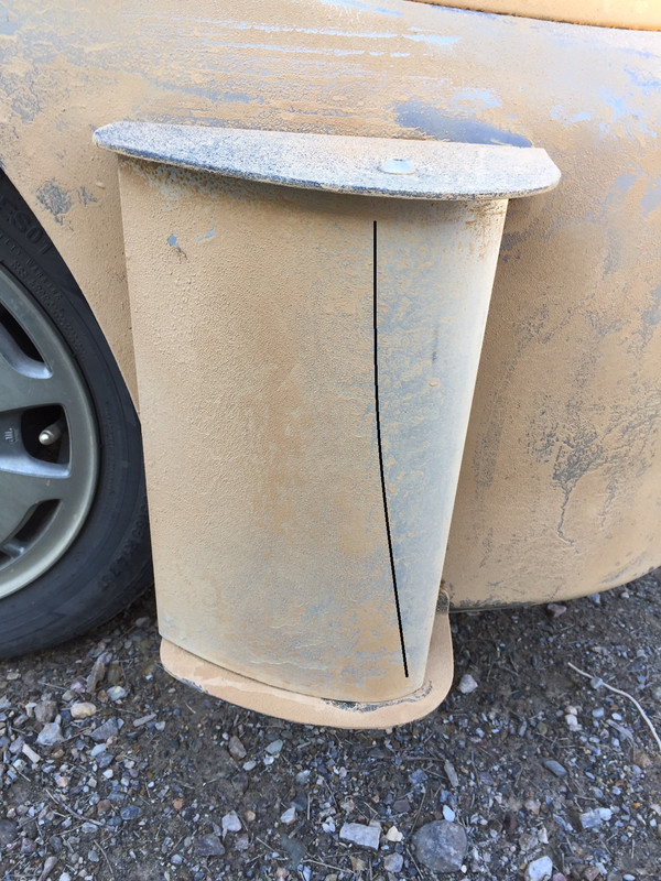
Edgarwit with my 'eroding clay' visualization technique.
Separation line marked on outside of aerofoil:
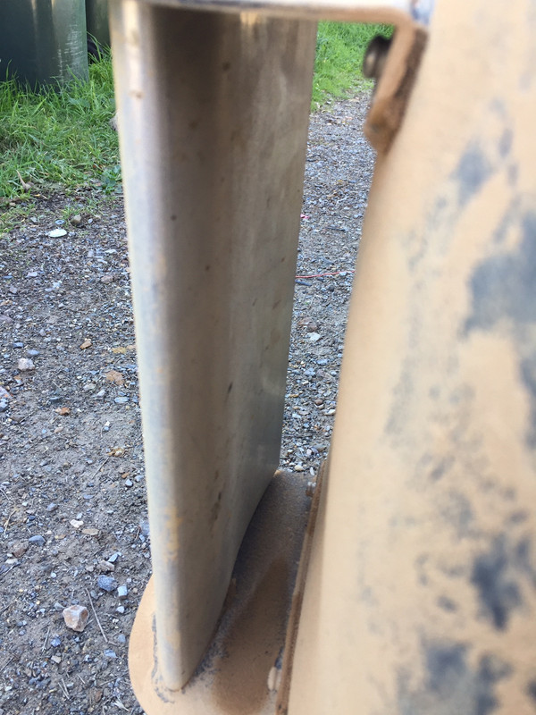
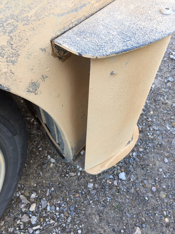
Vortex generated by sharp leading edge of endplate:

Completely clean inside surface of aerofoil:
Lack of removal of clay on bumper:
Testing done in windy conditions. |
|
|
|
|
The Following User Says Thank You to JulianEdgar For This Useful Post:
|
|
|
05-09-2020, 10:03 PM
|
#77 (permalink)
|
|
Master EcoModder
Join Date: Dec 2016
Location: Florida
Posts: 390
Thanks: 64
Thanked 163 Times in 138 Posts
|
The "expert" is correcting the terminology here I see. In that the device in use is effectively a "wing" designed to induce differential pressure, being used vertically when differential pressure has little use, which only adds to drag, size, weight, complexity, etc. An infinitely thin correctly configured "vane" would reduce all these issues, as I see it, what say the "expert"?
I see he included the description "constant" (regarding crossection?), that would be my starting place.
Last edited by j-c-c; 05-09-2020 at 10:08 PM..
Reason: clarifcation
|
|
|
|
|
05-09-2020, 10:14 PM
|
#78 (permalink)
|
|
Banned
Join Date: Nov 2017
Location: Australia
Posts: 2,060
Thanks: 107
Thanked 1,605 Times in 1,136 Posts
|
Quote:
Originally Posted by j-c-c
The "expert" is correcting the terminology here I see. In that the device in use is effectively a "wing" designed to induce differential pressure, being used vertically when differential pressure has little use, which only adds to drag, size, weight, complexity, etc. An infinitely thin correctly configured "vane" would reduce all these issues, as I see it, what say the "expert"?
I see he included the description "constant" (regarding crossection?), that would be my starting place.
|
The beauty of this world is that we can all try out different approaches and then share the results. If holding a constant cross-section and not using an aerofoil are your preferred approach, why not do both those things and tell us how you go? |
|
|
|
|
05-09-2020, 10:33 PM
|
#79 (permalink)
|
|
Master EcoModder
Join Date: Dec 2016
Location: Florida
Posts: 390
Thanks: 64
Thanked 163 Times in 138 Posts
|
I will, and while I do my pre test design, I will keep a close eye on F1 plethora of vertical "turning vanes" they use of mostly constant crossections.
|
|
|
|
|
05-09-2020, 10:38 PM
|
#80 (permalink)
|
|
Banned
Join Date: Nov 2017
Location: Australia
Posts: 2,060
Thanks: 107
Thanked 1,605 Times in 1,136 Posts
|
Great! I look forward to seeing what results you get.
|
|
|
|
|


