 09-11-2013, 09:49 AM
|
#151 (permalink)
|
|
EcoModding Lurker
Join Date: Jun 2013
Location: Pretoria, South Africa
Posts: 4
Thanks: 1
Thanked 0 Times in 0 Posts
|
Hi Adam,
It has been so hot here the last week, that for us summer is here, but that does not mean that it is winter in the northen half. 
Can you describe the problems with the input section and the under-voltage lockout?
I'm definitely interested, but it has been a while since I have done pcbs though. How do I email you? A PM? Not sure that I will be able to yet.
John
|
|
|

|
 Today Today
|
|
|
|
 Other popular topics in this forum...
|
|
|
|
|
09-11-2013, 04:06 PM
|
#152 (permalink)
|
|
ReVolt Enthusiast
Join Date: Jun 2009
Location: Michigan, USA
Posts: 239
Thanks: 97
Thanked 47 Times in 40 Posts
|
Quote:
Originally Posted by adamj12b

If your interested in working on the design, email me and I can send you the stuff you need to get some made, but I sill wont have time to work on it myself until winter at the earliest. -Adam
|
Hi Adam,
I might be interested in doing some work on your Controller too. I have some spare time now and could help you, let me know if your interested?
Just PM me for my email address if you want to send me what you have, and I'll look it over and get back with you.
I could help John with the ECAD, is your PCB design in Eagle?
-Marks
Last edited by sawickm; 09-12-2013 at 08:28 AM..
|
|
|
|
|
09-24-2013, 11:13 AM
|
#153 (permalink)
|
|
Master EcoModder
Join Date: Apr 2009
Location: Charlton MA, USA
Posts: 463
Thanks: 31
Thanked 183 Times in 94 Posts
|
OK, Emails about helping with the logic board have been sent. Let me know what you come up with.
Also,
Driver boards are open for ordering again. Head over to Uprising Logic | Uprising logic and power stage components for electric vehicles. to place your order. Once I hit the 10 board minimum, I will place the order and get the parts.
-Adam |
|
|
|
|
The Following 3 Users Say Thank You to adamj12b For This Useful Post:
|
|
|
09-24-2013, 07:27 PM
|
#154 (permalink)
|
|
EcoModding Apprentice
Join Date: Oct 2010
Location: southland NZ
Posts: 153
Thanks: 38
Thanked 86 Times in 55 Posts
|
Driver board
Hi Adam
I have just navigated the shoals of PayPal to order a driver board kit
I hope you get the 10 orders soon
We are in spring here and some motorsport events are coming - I need more amps!
|
|
|
|
|
09-25-2013, 03:00 AM
|
#155 (permalink)
|
|
EcoModding Lurker
Join Date: Jun 2013
Location: Pretoria, South Africa
Posts: 4
Thanks: 1
Thanked 0 Times in 0 Posts
|
Hi Adam,
Have you considered a 2 IGBT version of your driver? I saw that others also asked about it before. I have a couple of questions about the driver board. What diodes are you using with the gate resistors? How did you make the pads for the IGBTs? Just 3 overlapping pads? Were the PCB house happy with that?
Starting to work through the control board, I have a question about the precharge circuit, how does it work? Are the FET and your contactor switching the positive side of the battery? It looks like it from CAP+ label. But how does the FET, Q8 gets switched on and off? The +15V supply is referenced to the negative of the pack (PE), or did I get it all wrong? 
Thanks
John |
|
|
|
|
09-25-2013, 10:22 AM
|
#156 (permalink)
|
|
Master EcoModder
Join Date: Apr 2009
Location: Charlton MA, USA
Posts: 463
Thanks: 31
Thanked 183 Times in 94 Posts
|
Quote:
Originally Posted by jhay
Hi Adam,
Have you considered a 2 IGBT version of your driver? I saw that others also asked about it before. I have a couple of questions about the driver board. What diodes are you using with the gate resistors? How did you make the pads for the IGBTs? Just 3 overlapping pads? Were the PCB house happy with that?
Starting to work through the control board, I have a question about the precharge circuit, how does it work? Are the FET and your contactor switching the positive side of the battery? It looks like it from CAP+ label. But how does the FET, Q8 gets switched on and off? The +15V supply is referenced to the negative of the pack (PE), or did I get it all wrong?
Thanks
John |
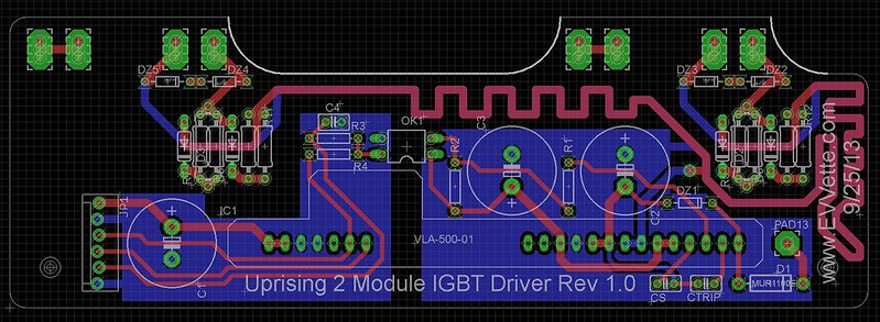 2 Module IGBT Driver
 by AdamBrunette, on Flickr
Here you go! 2 module version!
Email me for the eagle files if you want them.
As for the pads for the terminals, I just place 3 holes intersecting. It has not been a problem yet.
Diodes are MUR1100E.
The precharge circuit is as follows.
Pin 3 of the 23 pin connector is a connection to the B+ before contactors. This is feed through a 100R high power resistor, switched by Q8, an N channel MOSFET and then connects to the cap + terminal. The contactor output is justa 12V signal common to the 12V in the vehicle. The 15V dc-dc output shares a ground with the negative side of the capacitor. I dont think I realized this before. It was something I think I thought about thought about but did not correct because the Uprising driver has a second dc-dc and isolated the controls from the battery. I might need to look back into this. I dont want to add another dc-dc converter so the fet that switch's the precharge resistor. I didnt want to use the battery feed to power the fet as this would restrict what voltages could be used with the logic board. I want to be able to precharge anything between 12 and 400VDC.
-Adam
|
|
|
|
|
09-26-2013, 02:41 AM
|
#157 (permalink)
|
|
EcoModding Lurker
Join Date: Jun 2013
Location: Pretoria, South Africa
Posts: 4
Thanks: 1
Thanked 0 Times in 0 Posts
|
Hi Adam,
Quote:
Originally Posted by adamj12b
As for the pads for the terminals, I just place 3 holes intersecting. It has not been a problem yet.
|
I just read that some pcb houses do not like it because it breaks their drill bits. But maybe it is a bigger problem with smaller size drills.
I see D1, connecting to VCE of the VLA500 is a MUR1100E, but what about the others, D2-D7 in the gate drive part of the circuit? On the pcb they look smaller and on your schematic they do not have values.
Talking of the drive circuit, I see in the Semikron document, on page 44 they mention using resistors on the emitter side of the circuit too. Ever experimented with that? The document I read was:
www . evbmw . com / igbt.pdf
Quote:
The precharge circuit is as follows.
Pin 3 of the 23 pin connector is a connection to the B+ before contactors. This is feed through a 100R high power resistor, switched by Q8, an N channel MOSFET and then connects to the cap + terminal. The contactor output is justa 12V signal common to the 12V in the vehicle. The 15V dc-dc output shares a ground with the negative side of the capacitor. I dont think I realized this before. It was something I think I thought about thought about but did not correct because the Uprising driver has a second dc-dc and isolated the controls from the battery. I might need to look back into this. I dont want to add another dc-dc converter so the fet that switch's the precharge resistor. I didnt want to use the battery feed to power the fet as this would restrict what voltages could be used with the logic board. I want to be able to precharge anything between 12 and 400VDC.
|
That is how I read it, but wanted to make sure that I miss not miss something. One can probably use a small relay, like many other designs, the solid state would be nice though.
John |
|
|
|
|
09-28-2013, 11:48 PM
|
#158 (permalink)
|
|
EcoModding Lurker
Join Date: Feb 2010
Location: Detroit, MI
Posts: 18
Thanks: 1
Thanked 2 Times in 1 Post
|
I was planning on buying the 3 IGBT boards and just cutting them down. Will you build the 2 IGBT board if you get enough requests?
Thanks,
Darin
Quote:
Originally Posted by adamj12b
2 Module IGBT Driver by AdamBrunette, on Flickr
Here you go! 2 module version!
Email me for the eagle files if you want them.
As for the pads for the terminals, I just place 3 holes intersecting. It has not been a problem yet.
Diodes are MUR1100E.
The precharge circuit is as follows.
Pin 3 of the 23 pin connector is a connection to the B+ before contactors. This is feed through a 100R high power resistor, switched by Q8, an N channel MOSFET and then connects to the cap + terminal. The contactor output is justa 12V signal common to the 12V in the vehicle. The 15V dc-dc output shares a ground with the negative side of the capacitor. I dont think I realized this before. It was something I think I thought about thought about but did not correct because the Uprising driver has a second dc-dc and isolated the controls from the battery. I might need to look back into this. I dont want to add another dc-dc converter so the fet that switch's the precharge resistor. I didnt want to use the battery feed to power the fet as this would restrict what voltages could be used with the logic board. I want to be able to precharge anything between 12 and 400VDC.
-Adam
|
|
|
|
|
|
10-17-2013, 03:53 PM
|
#159 (permalink)
|
|
Master EcoModder
Join Date: Apr 2009
Location: Charlton MA, USA
Posts: 463
Thanks: 31
Thanked 183 Times in 94 Posts
|
Quote:
Originally Posted by badfishracing
I was planning on buying the 3 IGBT boards and just cutting them down. Will you build the 2 IGBT board if you get enough requests?
Thanks,
Darin
|
If you want to have the 2 module boards built, I can send you the eagle files. I dont think I will build any at this time.
Currently I have orders for 4 drivers. I need to make it to 6 to order the boards. If anybody wants them, Please place an order.
-Adam |
|
|
|
|
10-17-2013, 08:09 PM
|
#160 (permalink)
|
|
EcoModding Apprentice
Join Date: Oct 2010
Location: southland NZ
Posts: 153
Thanks: 38
Thanked 86 Times in 55 Posts
|
Hi Adam,
Can I order another board? - I almost certainly won't need it but I could pay for it now and if possible swap it for something else later
Would that help?
Duncan
|
|
|
|
|


