06-24-2017, 03:06 PM
|
#661 (permalink)
|
|
Master EcoModder
Join Date: Aug 2012
Location: northwest of normal
Posts: 29,415
Thanks: 8,367
Thanked 9,125 Times in 7,534 Posts
|
There it is! Bravo.
It reminds me of nothing so much as a faithful rendition of Thee Holy Template.
Maybe a little Dymaxion. 
|
|
|

|
|
The Following User Says Thank You to freebeard For This Useful Post:
|
|
 Today Today
|
|
|
|
 Other popular topics in this forum...
|
|
|
|
|
07-19-2017, 10:42 PM
|
#662 (permalink)
|
|
EcoModding Apprentice
Join Date: Dec 2011
Location: San Francisco, CA USA
Posts: 142
Thanks: 6
Thanked 53 Times in 31 Posts
|
I spent some time today in Rhino 3D trying to fit a smooth curve to the Aero Template. I started by using sections of ellipses to make it easy to have all of the curves with a zero angle at the starting/high point. Then I did an "extend line by arc" which starts with the arc tangent to a horizontal line at that maximum height point.
It looks to me like the angle numbers on the template have some problems. Perhaps I didn't find the most recent version of the template, I looked at the A, B and C threads. Maybe someone can spot where I've gone amiss. I've attached a screen capture from my spread sheet.
The small and medium ellipses have a common center (at the origin to match the template and height, the medium is longer in the horizontal axis. The large template is aligned with the origin but the center is dropped a fair bit because both horizontal and vertical dimensions are increased.
It seems to me that all the curves should start at zero and continually increase in angle in a smooth fashion. The template curve eventually stops increasing and goes to a straight, presumably tangent, line of 22 degree angle.
I didn't bother with the tangent line as that would probably start at different places on the different semi-elliptical curves and the anomaly was showing up in the early part of the curve.
On the template the 10%-increment station angles start at a 3.5 degree difference at 10% (3.5-0) go to a 2 degree delta at 20%, jump to a 6.5 degree delta at 30% and then back down to 3, 3.5, 2.5, 1 and 0 when the straight line kicks in.
The angles of the smaller ellipses become more vertical at about the 50-60% stations but the curve on the template is erratic well before that point.
The arc seems a pretty good fit to the template with the delta rising very slightly. It could be truncated at the 60% station where the value is 21.7612 degrees and go straight from that point.
I realize that most people are probably using the template tool and comparing it to photos, but if they are wanting to make something based on the angles shown they may have problem.
On the other hand, maybe if the shape was developed empirically it works better with a few spots where the curve gets rough.
ETA: the arc I used is roughly 162% of the total length of the template. I did it by eye so I'll go back later and make an arc that is an even 1.6x the length to see how that looks.
cheers,
Michael
Last edited by Michael Moore; 07-19-2017 at 10:53 PM..
|
|
|
|
|
The Following User Says Thank You to Michael Moore For This Useful Post:
|
|
|
07-19-2017, 11:27 PM
|
#663 (permalink)
|
|
Master EcoModder
Join Date: Sep 2012
Location: Motor City
Posts: 283
Thanks: 0
Thanked 227 Times in 139 Posts
|
I have my similar spreadsheet around somewhere. I posted some results, but images are stored in Photobucket.
I attached where I ended, and arc 5.56 times the height of the template. I think we agree, it's an arc.
|
|
|
|
|
07-20-2017, 12:01 AM
|
#664 (permalink)
|
|
EcoModding Apprentice
Join Date: Dec 2011
Location: San Francisco, CA USA
Posts: 142
Thanks: 6
Thanked 53 Times in 31 Posts
|
The angle numbers for a 1.6X length radius arc:
0, 3.5833, 7.1808, 10.8069, 14.4775, 18.21, 22.0243, 25.9445, 30.001 so that could be an extended straight line at the 60% station.
Delta's smoothly rise from 3.5833 to 3.8143 at 60%.
It looks like I'm getting 5.66X the height for the arc radius so that's pretty close agreement.
|
|
|
|
|
07-20-2017, 12:08 AM
|
#665 (permalink)
|
|
EcoModding Apprentice
Join Date: May 2008
Location: N. Saskatchewan, CA
Posts: 1,805
Thanks: 91
Thanked 460 Times in 328 Posts
|
It is a decade since I ran Rhino, but I seem to recall it being able to fit a smooth curve to a set of X-Y coordinates. Only the laminar flow shapes need a pure mathematical progression.
|
|
|
|
|
The Following User Says Thank You to Bicycle Bob For This Useful Post:
|
|
|
07-20-2017, 01:19 AM
|
#666 (permalink)
|
|
EcoModding Apprentice
Join Date: Dec 2011
Location: San Francisco, CA USA
Posts: 142
Thanks: 6
Thanked 53 Times in 31 Posts
|
Bob, I tried that with points I extracted from the template but once I turned on the curve analysis tools they proved to not be very smooth. I think the points have to be located properly to help the smoothness. Running the "fair curve" command several times helped, but the curve moved away from the template. The curves generated by the arc or ellipse commands are pretty much dead smooth, as I'd expect since they are mathematical constructs and not "let me guess that the point should go about here on this not very clear bitmap in the background."
|
|
|
|
|
07-20-2017, 06:00 AM
|
#667 (permalink)
|
|
Master EcoModder
Join Date: May 2011
Location: Syracuse, NY USA
Posts: 2,935
Thanks: 326
Thanked 1,315 Times in 968 Posts
|
The best airfoil generator I've found is at Wind and Wet.
.
Online airfoil plotter
. |
|
|
|
|
The Following 4 Users Say Thank You to sendler For This Useful Post:
|
|
|
07-22-2017, 01:16 PM
|
#668 (permalink)
|
|
Master EcoModder
Join Date: Jan 2008
Location: Sanger,Texas,U.S.A.
Posts: 16,534
Thanks: 24,520
Thanked 7,436 Times in 4,817 Posts
|
curves
Quote:
Originally Posted by Michael Moore

I spent some time today in Rhino 3D trying to fit a smooth curve to the Aero Template. I started by using sections of ellipses to make it easy to have all of the curves with a zero angle at the starting/high point. Then I did an "extend line by arc" which starts with the arc tangent to a horizontal line at that maximum height point.
It looks to me like the angle numbers on the template have some problems. Perhaps I didn't find the most recent version of the template, I looked at the A, B and C threads. Maybe someone can spot where I've gone amiss. I've attached a screen capture from my spread sheet.
The small and medium ellipses have a common center (at the origin to match the template and height, the medium is longer in the horizontal axis. The large template is aligned with the origin but the center is dropped a fair bit because both horizontal and vertical dimensions are increased.
It seems to me that all the curves should start at zero and continually increase in angle in a smooth fashion. The template curve eventually stops increasing and goes to a straight, presumably tangent, line of 22 degree angle.
I didn't bother with the tangent line as that would probably start at different places on the different semi-elliptical curves and the anomaly was showing up in the early part of the curve.
On the template the 10%-increment station angles start at a 3.5 degree difference at 10% (3.5-0) go to a 2 degree delta at 20%, jump to a 6.5 degree delta at 30% and then back down to 3, 3.5, 2.5, 1 and 0 when the straight line kicks in.
The angles of the smaller ellipses become more vertical at about the 50-60% stations but the curve on the template is erratic well before that point.
The arc seems a pretty good fit to the template with the delta rising very slightly. It could be truncated at the 60% station where the value is 21.7612 degrees and go straight from that point.
I realize that most people are probably using the template tool and comparing it to photos, but if they are wanting to make something based on the angles shown they may have problem.
On the other hand, maybe if the shape was developed empirically it works better with a few spots where the curve gets rough.
ETA: the arc I used is roughly 162% of the total length of the template. I did it by eye so I'll go back later and make an arc that is an even 1.6x the length to see how that looks.
cheers,
Michael
|
The template is derived from two different sources of artwork published for Cd 0.04,2.5:1 streamline bodies of revolution,provided by Franzini et al., and Wolf Heinrich Hucho.
One is 'slow' and one is 'faster'.
Some production car greenhouses lend them selves to one,but not the other so I published two,which hopefully satisfies any given production architecture.
It's not a 'perfect' solution but has a high degree of confidence for users as far as eliminating aft-body flow separation,critical for profile drag reduction.
__________________
Photobucket album: http://s1271.photobucket.com/albums/jj622/aerohead2/
|
|
|
|
|
The Following User Says Thank You to aerohead For This Useful Post:
|
|
|
08-30-2017, 05:06 AM
|
#669 (permalink)
|
|
EcoModding Lurker
Join Date: Aug 2017
Location: Brisbane, Australia
Posts: 26
Thanks: 1
Thanked 7 Times in 7 Posts
|
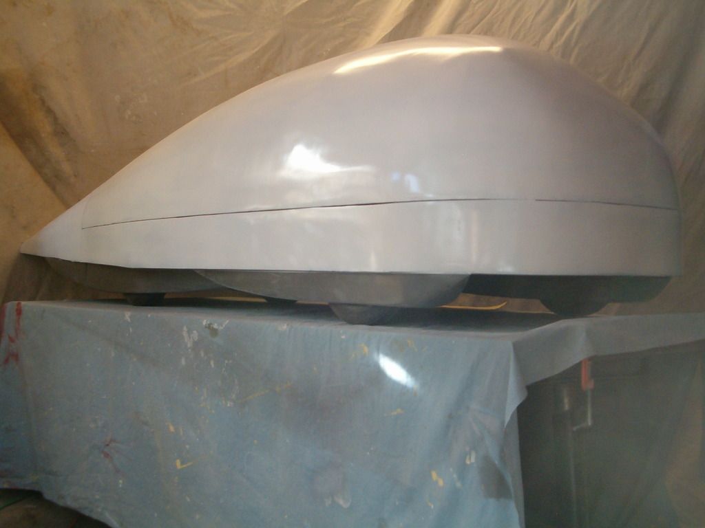
I've been looking at roof profiles, in relation to a potential motorhome as discussed in this thread: http://ecomodder.com/forum/showthrea...van-35515.html
In the below image are two roof profiles. The primary difference is how rounded they are just after the windscreen. Intuition tells me that the more rounded top would be the lower drag.
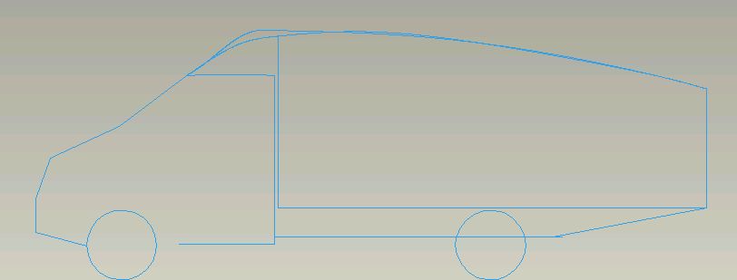
However, when I apply the template this thread is about, it tells me that the pointy one is better. Primarily because the downward taper starts significantly closer to the front of the vehicle (by roughly 10-12% of total vehicle length).
Pointy option - could even drop off steeper at the back for small tail cross section:
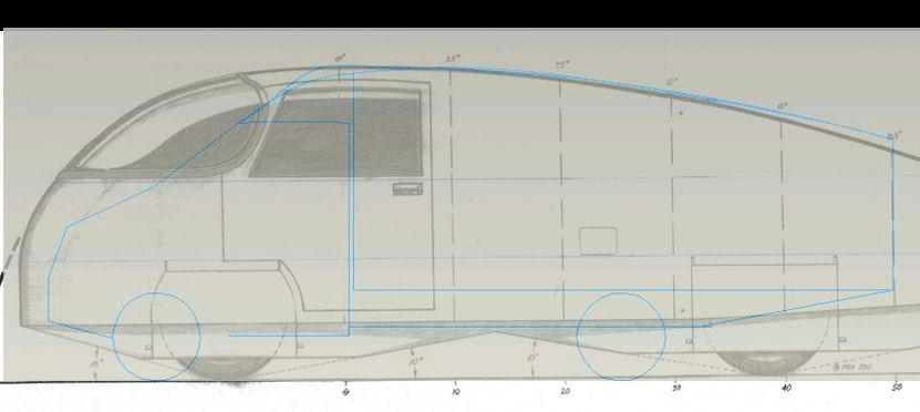
Rounded one - dropping off too quickly - needs larger tail cross section:
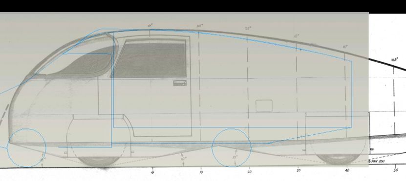
Post #604 in this thread has some modelling showing high pressure at the sharp point above the windscreen, which I think indicates rounding is better? (sure, I realise the front profile is quite different, but same general pattern probably applies)
Is the bluntness /sharpness of the front of the vehicle, and transition to the downward taper, really that insignificant relative to the position of the high point? Any comments/thoughts as to which is better? |
|
|
|
|
08-30-2017, 06:53 PM
|
#670 (permalink)
|
|
Master EcoModder
Join Date: Aug 2012
Location: northwest of normal
Posts: 29,415
Thanks: 8,367
Thanked 9,125 Times in 7,534 Posts
|
I wouldn't worry about it too much. The Template presumes taper in plan to equal the taper in elevation, and a half-circular cross section. The racer's aphorism is "It isn't how you punch the hole in the air, it's how you close the hole in the air." IOW the rear is more important than the front.
That said the bluff forebody of the Template insures the flow is uniform enough that it can support the taper without shedding vortexes. Any disruption such as the windshield header you mention can spoil airflow 'downstream'.
Why not go with the curved header and then a Tropfenwagen style rear with a flat top and tapered sides? It would have more interior space.
|
|
|
|
|