Go Back   EcoModder Forum > EcoModding > DIY / How-to
Register Now
 Register Now
 

Reply  Post New Thread
 
Submit Tools LinkBack Thread Tools
Old 02-14-2010, 10:23 PM   #31 (permalink)
Left Lane Ecodriver
 
RobertSmalls's Avatar
 
Join Date: Aug 2008
Location: Buffalo, NY, USA
Posts: 2,257

Prius C - '12 Toyota Prius C
Thanks: 79
Thanked 286 Times in 199 Posts
I suppose now is the time for criticism, before the design solidifies.

Have you made a chalk-and-lawn-furniture mockup of the seating arrangement? It's very unconventional, and I wonder how well it works.

There is too much unutilized width in your vehicle.

You should be able to lower your roofline a few inches by placing batteries below everyone's chair, and below nobody's feet.

Regarding the driver's on-center location: that's great for a race car, and it's good for side impact safety. However, road cars traditionally place the driver at the left side of the car (in LHD countries) so he can put the left wheels exactly where he wants them. A notable exception is driving in the alps. If cliffs are more of a concern than traffic, sitting on the RHS is preferred.


I am not an expert, but it looks like you need a LOT more room between the front bumper and the driver's feet. Check out your Scions. I bet that distance is just under a meter. Since your car will not be run through real or simulated crash tests, and you may have trouble managing zones of different stiffness, better to err on the side of caution and go with a 1m crumple zone.

I'm making several assumptions there about what you're going to do with the vehicle, and how safe it needs to be. A vehicle which is novel and awesome can get away with poor crash safety, as long as it's something you drive slowly, carefully, and seldom. Something daily driven in traffic and/or snow, needs to be safer (says a man whose Insight has been in two fender benders in four months).


If I can get my CFD software running, I'd be happy to run your 3D CAD model through it.
Quote:
Originally Posted by NeilBlanchard View Post
Thanks Bob -- I'm sorry to hear that! Yes 24X the air speed would be a big challenge! I guess that is why the pictures of the Mercedes scale models show them in a fluid tank? :-(
Can you build a water tank that supplies water at 15mph? Or maybe a 1/12 scale model and a stream of water at 7mph?

  Reply With Quote
Alt Today
Popular topics

Other popular topics in this forum...

   
Old 02-20-2010, 01:04 PM   #32 (permalink)
EcoModding Lurker
 
Join Date: Feb 2010
Location: Richmond, BC
Posts: 4

Bugsy - '13 Hyundai Veloster Turbo
Thanks: 0
Thanked 2 Times in 2 Posts
Wow!

I don't know anything about actual aerodynamics or design but this is a very, very interesting thread.

Neil, power to you for thinking big and good luck. I will be keeping my eye on this for sure.
  Reply With Quote
The Following User Says Thank You to Roundtable For This Useful Post:
NeilBlanchard (02-20-2010)
Old 02-20-2010, 03:53 PM   #33 (permalink)
...beats walking...
 
Join Date: Jul 2009
Location: .
Posts: 6,190
Thanks: 179
Thanked 1,525 Times in 1,126 Posts
...human shoulders are much wider than their heads, hence, "wrapping" the body slightly closer to passenger heads will greatly reduce "unused" width as well as overall body cross-sectional area.

...and, don't forget about "left-hand" drive people, so unusual offset seating might not be popularly acceptable.

...I *DO* however, like the *idea* of articulating front wheel covers, but wonder how well they might actually perform? Ok at lower speeds, but at highway speeds will they "balloon" and "parachute" and thus cause more drag than they're supposed to reduce? Nevertheless, the *idea* is excellent.

...with advent of airbags, one wonders *WHY* the auto industry hasn't gone back to tubing frames for weight and structural improvements? Nice thing about a tube is that it can simultaneously serve as a conduit for wires, hoses, cables, etc., heck even as exhaust piping!

Last edited by gone-ot; 03-01-2010 at 12:54 PM..
  Reply With Quote
Old 02-20-2010, 05:28 PM   #34 (permalink)
Master EcoModder
 
NeilBlanchard's Avatar
 
Join Date: May 2008
Location: Maynard, MA Eaarth
Posts: 7,907

Mica Blue - '05 Scion xA RS 2.0
Team Toyota
90 day: 42.48 mpg (US)

Forest - '15 Nissan Leaf S
Team Nissan
90 day: 156.46 mpg (US)

Number 7 - '15 VW e-Golf SEL
TEAM VW AUDI Group
90 day: 155.81 mpg (US)
Thanks: 3,475
Thanked 2,950 Times in 1,844 Posts
My hope and intention was to has the wheel skirts be sealed, even when they are pivoted out -- the inner fender, as it were, would slide out and maintain a closed cover. So, it would not be a parachute.
__________________
Sincerely, Neil

http://neilblanchard.blogspot.com/
  Reply With Quote
Old 02-20-2010, 05:39 PM   #35 (permalink)
...beats walking...
 
Join Date: Jul 2009
Location: .
Posts: 6,190
Thanks: 179
Thanked 1,525 Times in 1,126 Posts
...oops, that's what happens when the reader doesn't "read" the writers' mind correctly.
  Reply With Quote
Old 02-28-2010, 01:22 PM   #36 (permalink)
Master EcoModder
 
NeilBlanchard's Avatar
 
Join Date: May 2008
Location: Maynard, MA Eaarth
Posts: 7,907

Mica Blue - '05 Scion xA RS 2.0
Team Toyota
90 day: 42.48 mpg (US)

Forest - '15 Nissan Leaf S
Team Nissan
90 day: 156.46 mpg (US)

Number 7 - '15 VW e-Golf SEL
TEAM VW AUDI Group
90 day: 155.81 mpg (US)
Thanks: 3,475
Thanked 2,950 Times in 1,844 Posts
A brief update: Here's a Sonex airplane that my friend Mike Smith is building from scratch:

Sonex -- The Sport Aircraft Reality Check!

I think the 4-cylinder 80HP engine weighs ~130 pounds, and the dry weight of the whole plane (including the engine) is 570-620 pounds. 22' wingspan, and the fuselage is 18' long. +6G and -3G in a 440-490 pound structure is great! This construction method is pretty straightforward. It uses 0.025" and 0.032" 6061-T6 Aluminum sheets, and some aluminum plate and angle stock -- and thousands of pop rivets.


What my friend did is he drew the patterns full size in DataCAD (which the way you always draw things!) and he plotted them out full size (you can choose any scale for plotting) and he used spray adhesive to stick the paper onto the aluminum sheets. Then he cut them out, drilled all the holes, deburred them, clamped them in wood forms (two halves cut out of OSB board and wing nut and bolted) and used a soft plastic hammer and a pair of special pliers to pleat the flange around curves.

He's spent about 500 hours and he has almost all the components made. He's spent ~$1,600 on stock and ~$900 on tools.

Doing a similar process on a car would not seem to be all that hard.

Oh, and I'm continuing on the drawings -- I'd like to be able to test the aerodynamics of it before committing it to reality...or at least before building a working chassis!
__________________
Sincerely, Neil

http://neilblanchard.blogspot.com/

Last edited by NeilBlanchard; 02-28-2010 at 02:06 PM..
  Reply With Quote
The Following User Says Thank You to NeilBlanchard For This Useful Post:
Rokeby (02-28-2010)
Old 02-28-2010, 01:26 PM   #37 (permalink)
...beats walking...
 
Join Date: Jul 2009
Location: .
Posts: 6,190
Thanks: 179
Thanked 1,525 Times in 1,126 Posts
...sounds like the old "build-it yourself" MIDGET cars that were advertised in Popular Mechanics magazine.
  Reply With Quote
Old 03-01-2010, 11:42 AM   #38 (permalink)
Master EcoModder
 
NeilBlanchard's Avatar
 
Join Date: May 2008
Location: Maynard, MA Eaarth
Posts: 7,907

Mica Blue - '05 Scion xA RS 2.0
Team Toyota
90 day: 42.48 mpg (US)

Forest - '15 Nissan Leaf S
Team Nissan
90 day: 156.46 mpg (US)

Number 7 - '15 VW e-Golf SEL
TEAM VW AUDI Group
90 day: 155.81 mpg (US)
Thanks: 3,475
Thanked 2,950 Times in 1,844 Posts
Okay,

I added a bit more to the "shoulder" of the sides, and I sloped the side windows inward at the top, and the Area is reduced by about 0.9 sq ft; to about 24.976 sq ft.

I also will extend the lower center front out to give some more crumple space, and to make it less blunt aerodynamically. I'll post the revised drawings soon.
__________________
Sincerely, Neil

http://neilblanchard.blogspot.com/
  Reply With Quote
Old 03-01-2010, 12:53 PM   #39 (permalink)
Master EcoModder
 
NeilBlanchard's Avatar
 
Join Date: May 2008
Location: Maynard, MA Eaarth
Posts: 7,907

Mica Blue - '05 Scion xA RS 2.0
Team Toyota
90 day: 42.48 mpg (US)

Forest - '15 Nissan Leaf S
Team Nissan
90 day: 156.46 mpg (US)

Number 7 - '15 VW e-Golf SEL
TEAM VW AUDI Group
90 day: 155.81 mpg (US)
Thanks: 3,475
Thanked 2,950 Times in 1,844 Posts
Here's the new drawings:

The front bumper has moved 5" forward, and the front wheels have moved 3" forward. I've drawn the section at the highest point of the roof, and this is superimposed on the front view. The steel protection bars are shown in the section, and the larger circles are the cutouts in the web of the aluminum rib.
__________________
Sincerely, Neil

http://neilblanchard.blogspot.com/
  Reply With Quote
Old 03-02-2010, 11:24 PM   #40 (permalink)
Master EcoModder
 
NeilBlanchard's Avatar
 
Join Date: May 2008
Location: Maynard, MA Eaarth
Posts: 7,907

Mica Blue - '05 Scion xA RS 2.0
Team Toyota
90 day: 42.48 mpg (US)

Forest - '15 Nissan Leaf S
Team Nissan
90 day: 156.46 mpg (US)

Number 7 - '15 VW e-Golf SEL
TEAM VW AUDI Group
90 day: 155.81 mpg (US)
Thanks: 3,475
Thanked 2,950 Times in 1,844 Posts
I would like this to be an open source project. By that I mean, that if anybody would like to contribute, or take what I have and run with it -- as long as you keep me up to date, then great.

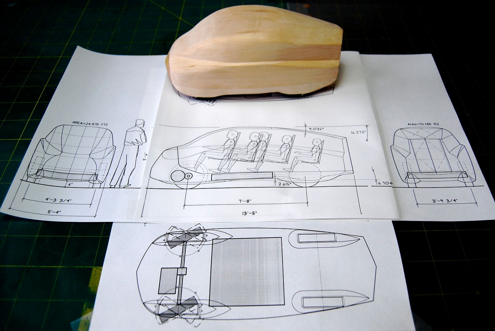
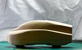
Here's a photo of the revised 1/24th scale (1/2" = 1') wooden model and the drawings that I've been working on:


Here's a start on the 3D model -- I have drawn what could be aluminum ribs that would be part of a monocoque chassis (very similar to the way acrobatic airplanes are made):


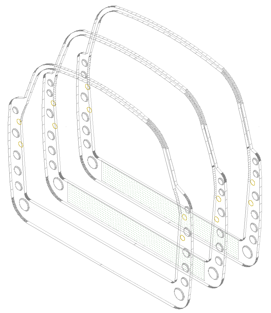
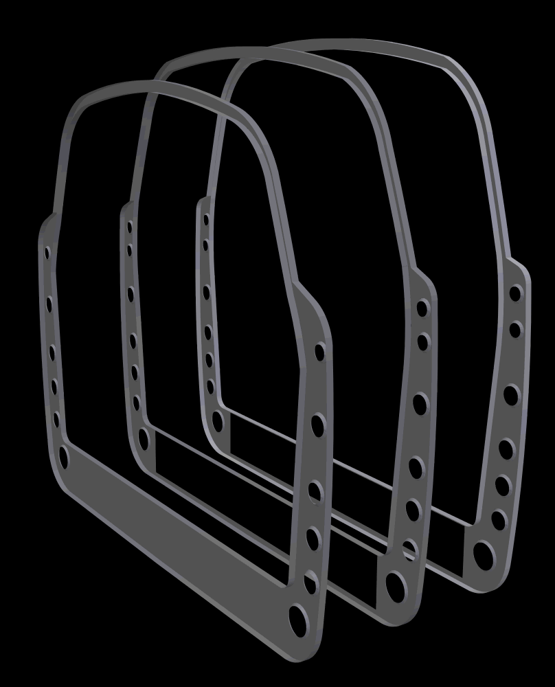
The rib on the right is at the highest point on the roof, and they are 1' apart (for modeling purposes, anyway). The large rectangular hole in the floor of the two is for the battery pack. The battery pack is the 4' square by 6" deep shaded rectangle on the drawings.

At this point, I'm thinking it would be better and faster to have my wooden model 3D scanned and have a mesh/surface model made. Does anyboy have any experience with this? Here's an outfit that can do it for ~$100-200: 3D Scan Services LLC - Affordable 3D Scanning and Reverse Engineering Services, but I'm hoping to find a place that is much closer to Massachusetts, where I live.

CarBEN Concept EV
An Open Source Project


Project Outline

Design and build an uber-efficient electric car; that has very low aerodynamic drag, as low weight as possible, is designed with good safety and crash protection, is practical to drive (i.e. it is not too big and has nimble handling), and I would like it to carry 4-5 people. By the way, the reason I chose the name CarBEN: it is a play on the word carbon (I want to not waste any), and the change in spelling are my initials backwards... :-)

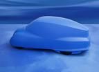
The basis for the aerodynamics is an early clay model of the Mercedes Bionic car (aka “Boxfish”) that was itself based on the boxfish. The tested coefficient of drag (Cd) of this model was an amazing 0.095 (Automotive Engineer PLUS - Mercedes-Benz) and it seems like a great place to start! The later Bionic car had a Cd of 0.19, which is still very good; but the open wheels and wider shape in the back are the primary reasons for the increase in drag. Another design that inspired a lot of the CarBEN design is the Schlörwagen – a very aerodynamic design from 1939.

My idea that will allow the wheels to remain covered, and therefore (hopefully) achieve a Cd nearer to the blue model than to the Bionic car, is to have articulated front wheel covers that move with the wheels in sharper turns. I'll get more into the details of how this could work later on.

To achieve low weight, I think the ideal structure would be carbon fiber reinforced plastic. But this is difficult for me to work with, as I have no experience with it, and I think the prospect of making molds and the fumes, etc. is daunting. I've also considered welding a steel tube chassis, and then make either a fiberglass or aluminum body. But I think this would be heavier, and while I have access to a MIG welder; it is not as good as an aluminum monocoque chassis.

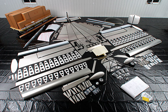
I got the idea for how to do this from seeing a friend who is building an airplane from scratch. It is a 2 seat acrobatic capable, and the dry weight (including the 4 cylinder 80HP engine) is between 570 and 620 pounds. I think the process he is using, which plotting out full size templates, and then forming the 6061-T6 sheets into the ribs and the skin; using wooden forms – makes a lot of sense to use this method to build this car.

Aluminum is fully recyclable, it is not dusty, has no fumes, and only requires a small bandsaw, a pair of “pleating” pliers, a soft hammer, and riveting tools. If I start with a 3D CAD model and drawings generated from that, the templates will be accurate. The resulting chassis should be lighter than I could manage with steel, and it forms the body at the same time.

Starting with the Sonex airplane (Sonex -- The Sport Aircraft Reality Check!) and its weight of 620 pounds (~130 pounds for the engine is included in that) – the 22' wingspan and 18' long fuselage have roughly similar surface area to my CarBEN design and so it should weigh about the same (490 pounds). The AC electric motor and mechanical drive train are maybe a little heavier than the plane's engine; say 150 pounds. Add the four wheels, brakes, and the suspension (say 250 pounds) and the battery pack (say 400 – 600 pounds), the seats (which will be quite light – more later) and miscellaneous stuff will add 150 pounds. The the total vehicle weight could be in the 1450-1650 pound range. I would be very happy with anything under 1800 pounds.

The first order of business is to get the overall chassis to be as low drag as possible: I can loft a 3D CAD model from the wooden model I have made, but I think it would be better/faster/cheaper to have the model 3D scanned and use the mesh model for virtual aerodynamic testing. A program that can do 3D flow would be very important to check the form and to adjust it to lower the drag as much as possible without making it impractical to drive. i.e. I'm 6'-4” and I want to fit comfortably, and I need to fit my family.

For the safety considerations, the first thing I am doing is making the structure surround the passengers, and in order not to weaken it with doors, like most cars do. Like all design decisions, this involves some compromise, and I have been considering what some other designers have done: both the VW 1L and the FVT eVaro have canopies (like a jet fighter airplane), so that the structure around the passengers is continuous; the compromise comes in inclement weather, as the roof is not over the seats. Another car design that uses an unusual door and entry method is the Loremo; the entire windshield and hood hinge up (from the front) and you step over the side and pull the door back down in place. This also involves the steering wheel and column hinging up and out of the way with the door. The passengers get in through the rear hatch (and they sit facing backwards).

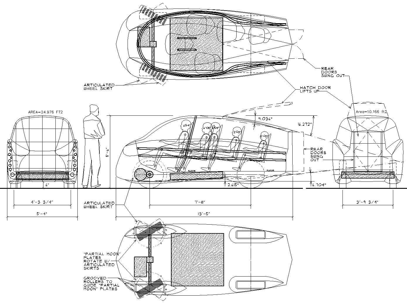
So, the initial door concept I am hoping to use is: in order to maintain a wraparound structure for safety, there is a single door in the rear of the CarBEN. It has two parts: a sloped hatch that is approximately the back 1/3 of the roof; it lifts up but remains (mostly) covering the opening from precipitation. The rear fascia of the car is a pair of small hinged doors that swing out. This is a a good a place as any to put in the drawing:
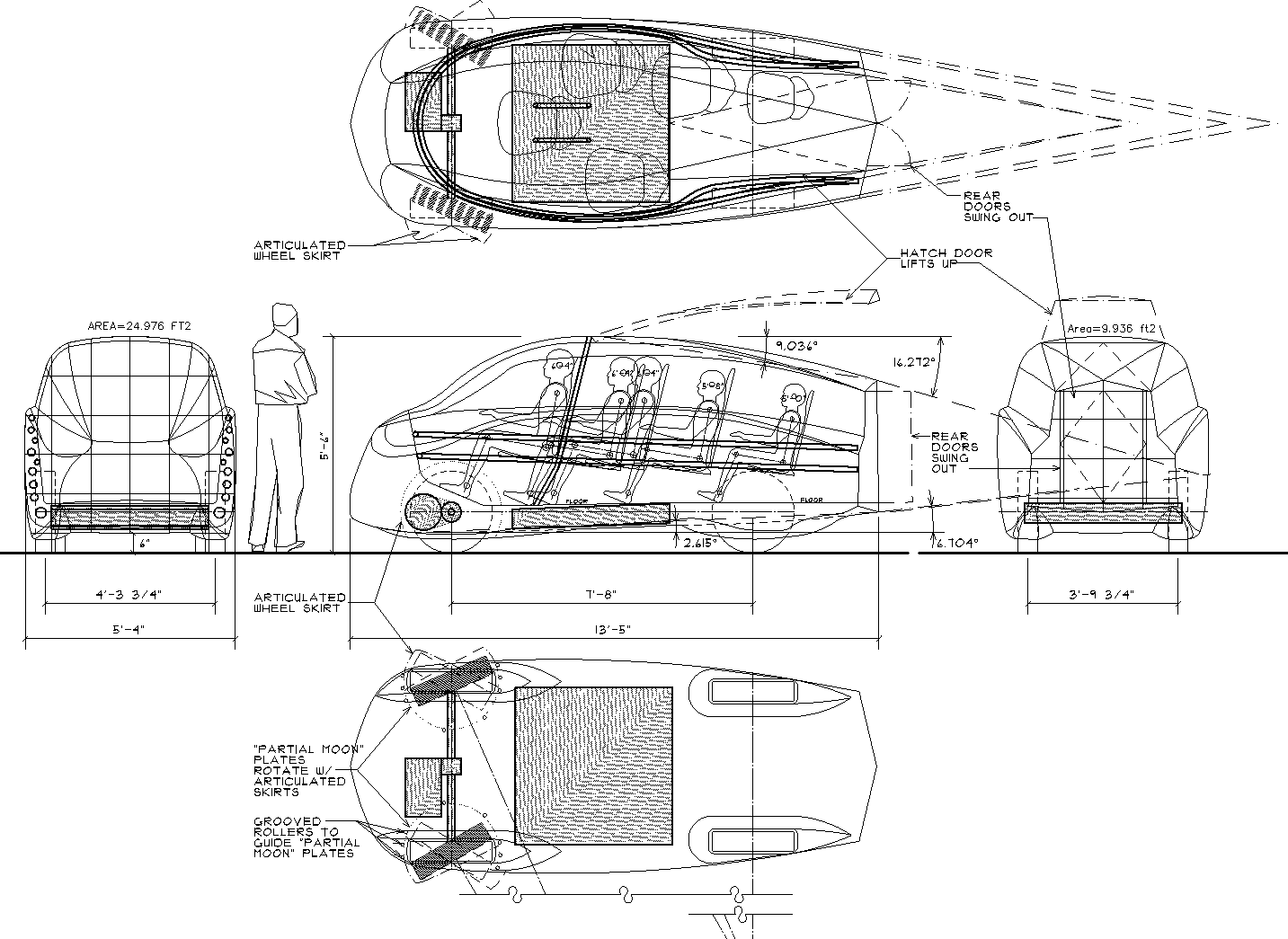
To get in the CarBEN, people would step up to the floor, and then turn to close the back doors, and the walk up the “aisle” to their seat. (This hopefully explains the staggered seat placement?) The overhead hatch would be closed – the details need to be worked out. If this door idea is not workable, or involves too much effort, then the fallback solution is to have conventional side doors – but I would use 3 or more latches (instead of the usual one) so that the door has 5 (or more) points of attachment (instead of the usual 3) so that the opening is not unduly weakened, and the passengers would be well protected from side impacts.

The other key solution to getting the CarBEN to work within a very low drag chassis, is the idea of articulated front wheel skirts (see the top, side and bottom views in the drawing). These consist of a ¾ moon panel on the bottom (shown with a dotted line) and another ¾ moon panel on the outside of the front wheel (also shown with a dotted line). There is a slot in the bottom panel where the wheel protrudes out, and there is an inner fender and curved panels that keep the wheel covered even when the steering is all the way to one lock or the other. The suspension motion of the wheel does not move the skirt assembly – the tire moves up and down through the slot and within the inner fender. The whole assembly pivots on grooved rollers around the edge of the bottom panel (see the small circles on the bottom view drawing) and a pivot at the top of the inner fender.

The steering pushrods are connected to the skirt assembly, and swing it with the wheel when the steering angle is sharper than needed for highway driving. So, at high speeds the aerodynamic shape remains unchanged, but at low(er) speeds when sharper steering angles are needed, the panels move to maintain clearance around the wheels. This is the biggest compromise made in the Schlörwagen design – they made the front wide enough to enclose the wheels even when they are at either steering lock. The Schlörwagen is 2.1 meters wide (6'-11”) which has a large affect on the area and hence the drag (CdA) and the car is wide; making it more difficult to drive. It also means there would be more body roll than would otherwise happen.

The battery pack (the 4' x 4' x 6”rectangle) should fit in the floor, between the four wheels. The AC electric drive train is a typical front wheel drive system; which will provide the best ability to have regenerative braking, to regain some of the power. I intend to use a super capacitor in parallel with the battery pack, which allows higher current to be absorbed from regenerative braking to be absorbed, and it can provide bursts of high current for acceleration, greatly reducing the battery load during charging and discharging, while driving. The folks at ChargeCar (at Carnegie Mellon) are working on enhancing this kind of system with “smart” programing that uses data from your commonly driven routes (using GPS to locate where you are driving) and elevation data to “anticipate” how to best manage the regenerated power, and to make the best use of the supercapacitor; as a power cache.

(to be continued)

__________________
Sincerely, Neil

http://neilblanchard.blogspot.com/

Last edited by NeilBlanchard; 03-11-2010 at 11:03 AM.. Reason: updated drawing
  Reply With Quote
Reply  Post New Thread


Powered by vBulletin® Version 3.8.11
Copyright ©2000 - 2024, vBulletin Solutions Inc.
Content Relevant URLs by vBSEO 3.5.2
All content copyright EcoModder.com