 03-02-2010, 11:39 PM
|
#41 (permalink)
|
|
EcoModding Apprentice
Join Date: May 2008
Location: N. Saskatchewan, CA
Posts: 1,805
Thanks: 91
Thanked 460 Times in 328 Posts
|
You'd save a lot of power and rubber by using ackerman steering geometry.
|
|
|

|
|
The Following User Says Thank You to Bicycle Bob For This Useful Post:
|
|
 Today Today
|
|
|
|
 Other popular topics in this forum...
|
|
|
|
 03-03-2010, 06:01 AM
|
#42 (permalink)
|
|
Master EcoModder
Join Date: May 2008
Location: Maynard, MA Eaarth
Posts: 7,908
Thanks: 3,475
Thanked 2,953 Times in 1,846 Posts
|
Hi Bob,
Thanks for that -- I need to explore suspension geometry, and alignment methods, as well.
Ackermann steering geometry - Wikipedia, the free encyclopedia |
|
|

|
 03-03-2010, 09:05 PM
|
#43 (permalink)
|
|
ecomonkey
Join Date: Dec 2009
Location: middleburg fl
Posts: 240
Thanks: 33
Thanked 30 Times in 21 Posts
|
you have strakes in front and rear of the front tires but only rears on the back tires? i thought fronts needed only leading strakes? and the rears leading and trailing,,is that the way the boxfish has them? i know its not super important to your design, just wondering,,, project looks good,, if you were down fl way id fire up the welder and help.
|
|
|

|
 03-03-2010, 09:50 PM
|
#44 (permalink)
|
|
Master EcoModder
Join Date: May 2008
Location: Maynard, MA Eaarth
Posts: 7,908
Thanks: 3,475
Thanked 2,953 Times in 1,846 Posts
|
No, I have strakes in front of and behind all the wheels. They are rounded in the from and somewhat pointed in the rear -- my woodnd model has out of scale strakes. The wheel wells are larger than they would be in real life, so the strakes are just approximate...
I'm strongly leaning towards a fabricated aluminum monocoque chassis, now -- see the long post above. Here's a continuation of it:
+++++++++++++++
In order for me to design a simple braking system (without the complexity of an integrated braking system), I would use two brake pedals: the center pedal would be a conventional brake pedal, that operates the hydraulic braking system. This would let the driver's habits be the default in a panic situation. The pedal on the left (about where the clutch would be in a manual shift car) would be the regenerative brake pedal. This would allow for a true coasting mode – both feet off of all pedals, that is easy an predictable. (This is key to good ecodriving; no matter what is powering the car.) Then, if some slowing is needed, the driver can use the regenerative brake as much as possible, and then use the hydraulic brake to supplement the regenerative brakes, if needed.
To save weight and space inside the car, I would make the seats with a mesh fabric stretched over frames; like some office chairs. This sort of seat are now being used in several concept cars, from VW, Toyota, and Honda for example. With the right ergonomics, these would be very comfortable, even for long trips, and they would “breathe”to help keep people cooler in the summer; reducing the need for other cooling methods.
I will try to make an effective passive air circulation system, with the intake(s) located in high velocity areas on the front or sides of the car, and I would provide for passive air extraction out the back of the car; exhausting into the low pressure wake zone at the back of the car. This could actually improve the drag a little; or at least minimize the increase due to the air flowing through the car. This passive air flow could also be tapped to cool the battery pack, and or the electric motor if needed.
The wheels and tires initially would be conventional, but instead of inflating the tires with air, I would use a foam – this would negate the need to keep track of the pressure, and it would probably minimize the rolling resistance, and tire wear would probably improve, because the temperatures would be kept low, since there would be virtually no flexing. The suspension would be designed to do all of the work (air inflated tires absorb a fair bit of the smaller bumps in the road), and it would provide very low rolling resistance. Later, I would install regenerative shock absorbers (apparently, these are currently being developed at Tufts University), and as much of the energy from the motion of the suspension as could be regained would help reduce the losses, by recharging the battery pack a little. (Rather than being wasted as heat in the tires and in conventional hydraulic shock absorbers.)
|
|
|

|
 03-11-2010, 11:01 AM
|
#45 (permalink)
|
|
Master EcoModder
Join Date: May 2008
Location: Maynard, MA Eaarth
Posts: 7,908
Thanks: 3,475
Thanked 2,953 Times in 1,846 Posts
|
Painted revised model!
|
|
|

|
 03-11-2010, 03:38 PM
|
#46 (permalink)
|
|
Master EcoModder
Join Date: May 2008
Location: Maynard, MA Eaarth
Posts: 7,908
Thanks: 3,475
Thanked 2,953 Times in 1,846 Posts
|
So, I was ready some of the the links that someone on the Aptera forum posted, and all of these look like they would require some major work, and programming in Linux is not my strong point. (Also, my best Linux machine had some shorts and is no longer with us...and my remaining Linux machine is about 6 or 7 years old Athlon XP with 768MB of RAM.)
So, if I get a model (I hope that I might in a week or two), can anybody point the way to getting it tested in a system that has a 3D CFD already up and running? |
|
|

|
 03-15-2010, 08:54 PM
|
#47 (permalink)
|
|
Master EcoModder
Join Date: May 2008
Location: Maynard, MA Eaarth
Posts: 7,908
Thanks: 3,475
Thanked 2,953 Times in 1,846 Posts
|
Hi,
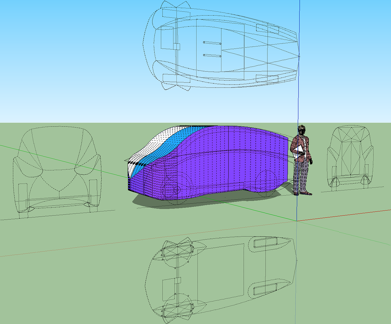
I used the DWG and got the main profiles modeled in SketchUp:

The orthographic drawing is up in the vertical plane, FYI. |
|
|

|
 03-15-2010, 10:08 PM
|
#48 (permalink)
|
|
Left Lane Ecodriver
Join Date: Aug 2008
Location: Buffalo, NY, USA
Posts: 2,257
Thanks: 79
Thanked 287 Times in 200 Posts
|
Quote:
Originally Posted by NeilBlanchard

So, I was ready some of the the links that someone on the Aptera forum posted, and all of these look like they would require some major work, and programming in Linux is not my strong point. (Also, my best Linux machine had some shorts and is no longer with us...and my remaining Linux machine is about 6 or 7 years old Athlon XP with 768MB of RAM.)
So, if I get a model (I hope that I might in a week or two), can anybody point the way to getting it tested in a system that has a 3D CFD already up and running? |
I've tried my hand at two different types of CFD.
There are a few simple CFD programs out there, like SolidWorks FloWorks Express, whose only output is visual. But FloWorks Express only displays a small number of streamlines, or pressure gradients that were probably generated at very low resolution, and displayed with lots of interpolation. FloWorks Express takes about a minute of CPU time (instead of many hours) to run its solver. How detailed of a model could that possibly be?
There are other, much simpler CFD and flow illustrator programs, some of which even run in a web browser.
The other kind of program I've tried is the proper CFD suite, like OpenFOAM or Ansys ICEM. Many of the solvers they use have been scientifically validated, i.e. the results of real wind tunnel tests were compared against the ouput of the solver, and the amount of accuracy was established.
OpenFOAM is very difficult to get into. You do need some programming and some engineering background. I've given up on it.
ICEM is relatively easy, but it's far from user-friendly. However, I could not for the life of me get the mesher to generate a valid mesh, so I never got the simulation to run. But if you can get me a mesh, I'll run it through the solver.
Someone on Eng-Tips.com recommended ANSYS Fluent, saying it comes with tutorials that'll have you running basic simulations in half an hour. Maybe I'll check if my alma mater has Fluent, and if I can get access to the right computer lab.
Good luck with CFD, and let us know what you come up with. |
|
|

|
 03-18-2010, 12:58 AM
|
#49 (permalink)
|
|
Master EcoModder
Join Date: May 2008
Location: Maynard, MA Eaarth
Posts: 7,908
Thanks: 3,475
Thanked 2,953 Times in 1,846 Posts
|

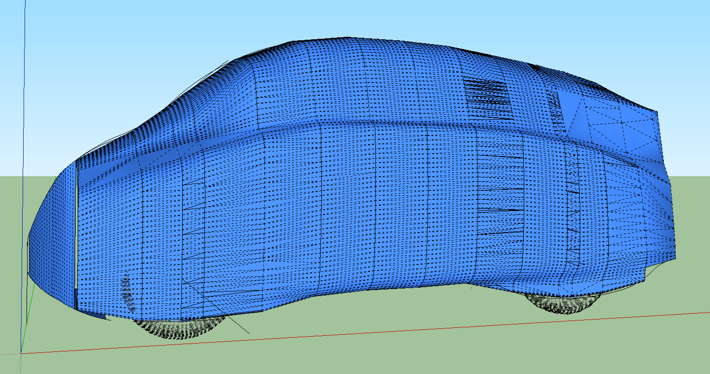
Okay, it is time for me to go to bed -- but this is a lot of fun! This is a *very* unfinished 3D model of my CarBEN EV concept design. I did 15 section in DataCAD, and used the Ruled Surface tool on as many of them as would "behave" -- it did about 2/3 of all these polygons. And then I had to use the Pencil tool in ...SketchUp to form the rest of them... whew!
|
|
|

|
 03-19-2010, 12:07 AM
|
#50 (permalink)
|
|
Master EcoModder
Join Date: May 2008
Location: Maynard, MA Eaarth
Posts: 7,908
Thanks: 3,475
Thanked 2,953 Times in 1,846 Posts
|
|
|
|

|
|