05-10-2010, 07:26 PM
|
#1 (permalink)
|
|
Master EcoModder
Join Date: Aug 2008
Location: The Wet Coast, Kanuckistan.
Posts: 1,275
Thanks: 100
Thanked 306 Times in 178 Posts
|
Underbody Flow Simulation Images
Interesting simulations of underbody flows
Quote:
Drag Reduction
One of the most important areas of work is drag reduction. Rieter uses Harpoon to help with this. A production car with two different underfloors (see images above), were compared. A drag reduction of 10% (Cd 0.33 to 0.30) was discovered using Harpoon with a new, flatter underbody concept.
|
Harpoon speeds up CFD analysis at Rieter Automotive
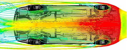
Underbody Streamlines for Cd = 0.33 (floor 1)
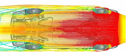
Underbody Streamlines for Cd = 0.30 (floor 2)
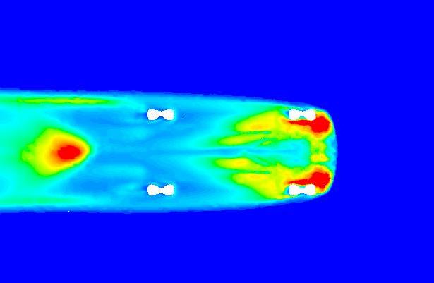
Underbody turbulent kinetic energy for Cd = 0.33 (floor 1)
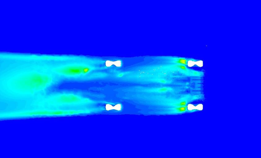
Underbody turbulent kinetic energy for Cd = 0.30 (floor 2)
__________________
Vortex generators are old tech. My new and improved vortex alternators are unstoppable.
"Its easy to explain how rockets work but explaining the aerodynamics of a wing takes a rocket scientist.


|
|
|

|
|
The Following 7 Users Say Thank You to orange4boy For This Useful Post:
|
|
 Today Today
|
|
|
|
 Other popular topics in this forum...
|
|
|
|
|
05-10-2010, 09:56 PM
|
#2 (permalink)
|
|
Left Lane Ecodriver
Join Date: Aug 2008
Location: Buffalo, NY, USA
Posts: 2,257
Thanks: 79
Thanked 286 Times in 199 Posts
|
I'm looking at this image and asking myself where the tire deflectors should go. This particular (probably fictious) car has net outward flow behind its front wheels, so a boattail behind each wheel should be angled accordingly.
At the rear, the picture is less clear, but I think the fairings need to point somewhat inwards. Hmm... tuft test before you add wheel fairings.
|
|
|
|
|
05-10-2010, 11:51 PM
|
#3 (permalink)
|
|
Master EcoModder
Join Date: Mar 2008
Location: USA
Posts: 568
Thanks: 1
Thanked 73 Times in 58 Posts
|
Those flow lines do not agree with the Hucho wind tunnel photo of the Calibra, which shows smoke trail flowing obliquely outboard under the nose.
Best to do tuft testing of your car on a normal road, recorded by minicam plugged into a laptop.
|
|
|
|
|
05-11-2010, 01:42 PM
|
#4 (permalink)
|
|
Master EcoModder
Join Date: Feb 2008
Location: belgium
Posts: 663
Thanks: 14
Thanked 61 Times in 44 Posts
|
i'm not sure how to read these images, but if these lines represent the path of air mollecules than the drawing only illustrates the path off a portion of the air that would hit the car, so air outside of these lines will likely form an even bigger wake outside of the wheels than what's illustrated.
so air that starts directly in front of the tires seems to need to go round the outside. that might also be what you see in the calibra image.
__________________
aer·o·dy·nam·ics: the science of passing gass
*i can coast for miles and miles and miles*
|
|
|
|
|
05-11-2010, 05:59 PM
|
#5 (permalink)
|
|
Master EcoModder
Join Date: Jan 2008
Location: Sanger,Texas,U.S.A.
Posts: 15,895
Thanks: 23,972
Thanked 7,223 Times in 4,650 Posts
|
pressure?
Quote:
Originally Posted by lunarhighway

i'm not sure how to read these images, but if these lines represent the path of air mollecules than the drawing only illustrates the path off a portion of the air that would hit the car, so air outside of these lines will likely form an even bigger wake outside of the wheels than what's illustrated.
so air that starts directly in front of the tires seems to need to go round the outside. that might also be what you see in the calibra image.
|
Do the different colors connote 'isobars' of differing pressure,rather than the actual stream flow? |
|
|
|
|
05-11-2010, 10:05 PM
|
#6 (permalink)
|
|
EcoModding Apprentice
Join Date: Sep 2009
Location: Northeast
Posts: 147
Thanks: 7
Thanked 18 Times in 12 Posts
|
Quote:
Originally Posted by aerohead
Do the different colors connote 'isobars' of differing pressure,rather than the actual stream flow?
|
Per the following link to NASA: Definition of Streamlines it appears the streamline pics show the path of the air molecules themselves. Pretty neat information right there, thanks for posting it orange4boy |
|
|
|
|
The Following User Says Thank You to tim3058 For This Useful Post:
|
|
|
05-12-2010, 05:17 AM
|
#7 (permalink)
|
|
Master EcoModder
Join Date: Feb 2008
Location: belgium
Posts: 663
Thanks: 14
Thanked 61 Times in 44 Posts
|
if the paths do illustrate the air molecules than i assume the colors are the speed, with red being fast, and blue slow. looking at the first two images the biggest image i see is illustration 2 has faster moving air underneath the front of the car. the bigest improvement that can be made to most underbody is installing a front undertray and often this is combined with the deletion or reduction of the central airdam on production cars (i've seen this mentioned with the calibra for the first time)and ie most low drag mercs all have this too. this site (in german) has quite some interesting data on the developement along with the image that shows the wake of the front tires
so making air move faster under the car appears to be a good thing based on my interpretation of this data.
Quote:
|
I'm looking at this image and asking myself where the tire deflectors should go. This particular (probably fictious) car has net outward flow behind its front wheels, so a boattail behind each wheel should be angled accordingly.
|
Do you mean a boattail that would support this flow direction? if so you're assuming this ourward flow is a good thing, however is causes the air to slow down... what would happen if two partial "side skirts" (or boattails) where placed behind and on the inside of the front wheels crating a duct and preventing the air from moving out. if the air can't move out it can only move backwards so it's speed will remain relatively high and the pressure low. this would stabilise the car in the first place, but also as the low pressure behind the wheels isn't "fed" with air from underneath the car, it might pull in air from the side of the car, thus decreasing the wake. dams in front of the rear wheels designed to guide air under the car might further help decrease the wake.
__________________
aer·o·dy·nam·ics: the science of passing gass
*i can coast for miles and miles and miles*
|
|
|
|
|
05-12-2010, 11:43 AM
|
#8 (permalink)
|
|
Aero Wannabe
Join Date: Dec 2007
Location: NW Colo
Posts: 738
Thanks: 705
Thanked 218 Times in 169 Posts
|
Side Skirts
Quote:
Originally Posted by lunarhighway
so making air move faster under the car appears to be a good thing based on my interpretation of this data.
Do you mean a boattail that would support this flow direction? if so you're assuming this ourward flow is a good thing, however is causes the air to slow down... what would happen if two partial "side skirts" (or boattails) where placed behind and on the inside of the front wheels crating a duct and preventing the air from moving out. if the air can't move out it can only move backwards so it's speed will remain relatively high and the pressure low. this would stabilise the car in the first place, but also as the low pressure behind the wheels isn't "fed" with air from underneath the car, it might pull in air from the side of the car, thus decreasing the wake. dams in front of the rear wheels designed to guide air under the car might further help decrease the wake.
|
I added side skirts attached to the rocker panels and small dams in front of the rear tires last spring. My fuel log seems to show an improvement in mpg. From what I have read, it is better to keep air under the car flowing backward to help fill in the trailing wake.
__________________
60 mpg hwy highest, 50+mpg lifetime
TDi=fast frugal fun  https://ecomodder.com/forum/showthre...tml#post621801

Quote:
Originally Posted by freebeard
The power needed to push an object through a fluid increases as the cube of the velocity. Mechanical friction increases as the square, so increasing speed requires progressively more power.
|
|
|
|
|
|
05-13-2010, 11:26 AM
|
#9 (permalink)
|
|
Master EcoModder
Join Date: Mar 2008
Location: USA
Posts: 568
Thanks: 1
Thanked 73 Times in 58 Posts
|
Quote:
Originally Posted by COcyclist
I added side skirts attached to the rocker panels and small dams in front of the rear tires last spring. My fuel log seems to show an improvement in mpg. From what I have read, it is better to keep air under the car flowing backward to help fill in the trailing wake.
|
In that case, flow fences should work well.
These could be made with 4" square PVC roof gutter drain pipe, cut diagonally corner to corner, to make 2 L shaped pieces. Then use those to clamp and secure the Coroplast sheeting to the underbody.
These could feed the diffuser vanes at the rear, or just act as long diffuser vanes going front to rear.
Such 4" square PVC drain pipe might make pretty good rocker skirts, too. Cheap. light, easy to work with, easy to find at Home Depot, etc..
However, another school of thought holds that undercar flow spreads laterally and such dispersal means less air under the car dragging against the underbody and giving the car unwanted lift. In that case, maybe it's best to use the flow fences to channel the undercar air obliquely out the sides.
Probably best to apply undertray, then tuft test to video actual airflow patterns at highway speed, then install wheel fairings/strakes at whatever orientations best enhance the flow.
Thoughts? |
|
|
|
|
05-13-2010, 05:13 PM
|
#10 (permalink)
|
|
Aero Wannabe
Join Date: Dec 2007
Location: NW Colo
Posts: 738
Thanks: 705
Thanked 218 Times in 169 Posts
|
Quote:
Originally Posted by Otto
However, another school of thought holds that undercar flow spreads laterally and such dispersal means less air under the car dragging against the underbody and giving the car unwanted lift. In that case, maybe it's best to use the flow fences to channel the undercar air obliquely out the sides.
Probably best to apply undertray, then tuft test to video actual airflow patterns at highway speed, then install wheel fairings/strakes at whatever orientations best enhance the flow.
Thoughts?
|
I guess that would depend on whether the main goal is to reduce lift at racing speeds or to reduce drag and lift at highway speeds. I think in my case a smooth underbody that angles upward to the rear of the car can act as a diffuser to help fill the wake and reduce lift. Basjoos uses inner and outer fences between the front and rear wheels to reduce turbulence from the tires. It's hard to argue with his results. I hope to test this myself as soon as I get a free weekend.
__________________
60 mpg hwy highest, 50+mpg lifetime
TDi=fast frugal fun
https://ecomodder.com/forum/showthre...tml#post621801
Quote:
Originally Posted by freebeard
The power needed to push an object through a fluid increases as the cube of the velocity. Mechanical friction increases as the square, so increasing speed requires progressively more power.
|
|
|
|
|
|