05-27-2022, 04:21 PM
|
#61 (permalink)
|
|
Master EcoModder
Join Date: Aug 2012
Location: northwest of normal
Posts: 29,413
Thanks: 8,367
Thanked 9,125 Times in 7,534 Posts
|
Tangents are not normal! [trigonometry joke]
In my understanding, they're the same except angles are measured from the end and tangents are measured from the middle.
A Bexzier curve has four points, two end points and two control points. The Golden Ratio is dimensionless.
__________________
.
.Without freedom of speech we wouldn't know who all the idiots are. -- anonymous poster
___________________
.
.tragectory: Line goes down and to the right.
Last edited by freebeard; 05-27-2022 at 08:24 PM..
|
|
|

|
|
The Following User Says Thank You to freebeard For This Useful Post:
|
|
 Today Today
|
|
|
|
 Other popular topics in this forum...
|
|
|
|
|
05-27-2022, 05:21 PM
|
#62 (permalink)
|
|
EcoModding DIY aer.or
Join Date: Oct 2020
Location: Virginia City, NV
Posts: 82
Thanks: 93
Thanked 69 Times in 57 Posts
|
Quote:
Originally Posted by freebeard

A Bexier curve has four points, two end points and two control points. The Golden Ratio is dimensionless.
|
Be zier curve?  |
|
|
|
|
The Following User Says Thank You to sregord For This Useful Post:
|
|
|
05-27-2022, 05:32 PM
|
#63 (permalink)
|
|
EcoModding DIY aer.or
Join Date: Oct 2020
Location: Virginia City, NV
Posts: 82
Thanks: 93
Thanked 69 Times in 57 Posts
|
|
|
|
|
|
05-27-2022, 08:23 PM
|
#64 (permalink)
|
|
Master EcoModder
Join Date: Aug 2012
Location: northwest of normal
Posts: 29,413
Thanks: 8,367
Thanked 9,125 Times in 7,534 Posts
|
Bezier curves are the most economical representation of any arbitrary curve. More than you want to know:
__________________
.
.Without freedom of speech we wouldn't know who all the idiots are. -- anonymous poster
___________________
.
.tragectory: Line goes down and to the right.
|
|
|
|
|
The Following User Says Thank You to freebeard For This Useful Post:
|
|
|
05-27-2022, 11:35 PM
|
#65 (permalink)
|
|
Human Environmentalist
Join Date: Aug 2010
Location: Oregon
Posts: 13,046
Thanks: 4,379
Thanked 4,558 Times in 3,504 Posts
|
Tangents can be normal, even if unlikely.
Tangents are always normal when I'm involved.
|
|
|
|
|
The Following User Says Thank You to redpoint5 For This Useful Post:
|
|
|
05-28-2022, 11:06 AM
|
#66 (permalink)
|
|
Master EcoModder
Join Date: Aug 2012
Location: northwest of normal
Posts: 29,413
Thanks: 8,367
Thanked 9,125 Times in 7,534 Posts
|
Explaining jokes ruins them. I'll just leave this:
Quote:
Normal
Geometry
In geometry, a normal is an object such as a line, ray, or vector that is perpendicular to a given object. For example, the normal line to a plane curve at a given point is the line perpendicular to the tangent line to the curve at the point.Wikipedia
|
__________________
.
.Without freedom of speech we wouldn't know who all the idiots are. -- anonymous poster
___________________
.
.tragectory: Line goes down and to the right.
|
|
|
|
|
The Following User Says Thank You to freebeard For This Useful Post:
|
|
|
05-31-2022, 11:08 AM
|
#67 (permalink)
|
|
Master EcoModder
Join Date: Jan 2008
Location: Sanger,Texas,U.S.A.
Posts: 16,534
Thanks: 24,520
Thanked 7,436 Times in 4,817 Posts
|
diffuser angle
Quote:
Originally Posted by sregord
I'll keep posting...see if what I find is helpful.
It may be redundant ...but where I have found the EcoModder Forum Link(s) I'll include them.
I did a quick read thru the Orbywan's RV mods(Boattail & belly pan), very nice builds, a true craftsman.
https://ecomodder.com/forum/showthre...d-e-18151.html
...surprised that the underside smoothing didn't have more impact.
https://ecomodder.com/forum/showthre...n-s-18427.html
Being familiar with racecar aerodynamic history, and changes from the early 60s(if it LOOKS aerodynamic) to Jim Hall's Chaparrals of the late 60s...and then the crazy downforce numbers of the late 80s(Nissan blowing tires & Spice collapsing suspension components) Mulsanne's Corner: Road Atlanta 1992, Rough and Tumble, attributed mostly to the underbelly's relationship with a diffuser. Today's endurance motorsports, is designed for "enough" downforce, and more efficiency(limited fuel capacity) than ever. https://www.racecar-engineering.com/...ta-ts050-2019/
How to connect any of this to a rounded corner big box/brick is a challenge.
We are working with something that is not <3" off the ground, or moving at over 75mph. ...but efficiency is what the goal is, not making the vehicle aerodynamically heavier.
Regarding the BellyPan: "pulling" air thru the underside with a <15*(degree) angled diffuser at the rear, with strakes ...extended into the(now revised bottom) boattail?. The other issue IS the "in the way" straight axle & rearend. Mulsanne's Corner: 1991-1993 Toyota Eagle MkIII
Don't you wish you could afford carbon fiber?
Regarding the Boattail addition, nice, clean, updated... obviously functional. Again Orbywan, a real craftsman.
It would be interesting if a measurement of the constructed angle from the sides & top is available. For reference... the NASA data:
https://www.nasa.gov/centers/dryden/...ain_H-2283.pdf
...doesn't reference a "best" boattail angle from the side or top. I did a little more checking and found:
https://doi.org/10.1155/2020/7580174
and
https://www.vortaflow.com/consulting...0reduction.pdf
The angle needs to be around 16* before separation of airflow. Funny there's that 15-16* again. I saw Aerohead had mentioned this number. 20-22* is too much but maybe less important at <75mph? Question: Does a curved side/top "inflated" boattail basically compound that 15* to a point? Has the group found more info about this? |
1) Three different researchers reported optimum drag reduction only with a 'long' diffuser of 'small' upsweep angle ( around 2.8-degrees )
2) Drag reduction for a 'short' diffuser occurred at a 4-degree upsweep.
3) W.H. Hucho mentions A.R. George's research of high underbody angles from June 18-20 ASME-CSME- Conference, 1979. These steep angles induced a counter-rotating pair of vortices, which induced an upwash, as a prismatic fastback would create a 'downwash'. If the vehicle already had an upper set of counter-rotating vortices, the lower set could be tuned to mitigate some of the vortex drag of the uppers. Any vorticity kills any chance of pressure recovery. It all becomes heat. Softened edges as on Orbywan's boat tail will prevent vortex formation in the first place, according to Carver-Funderburk at Texas Tech University.
----------------------------------------------------------------------------------
4) As to 'angles', they're completely contextual. If you're doing a simple angle, then, the 'optimum' angle will be a function of the proportion of the length of the tail, in comparison to the overall length of the vehicle. A percentage.
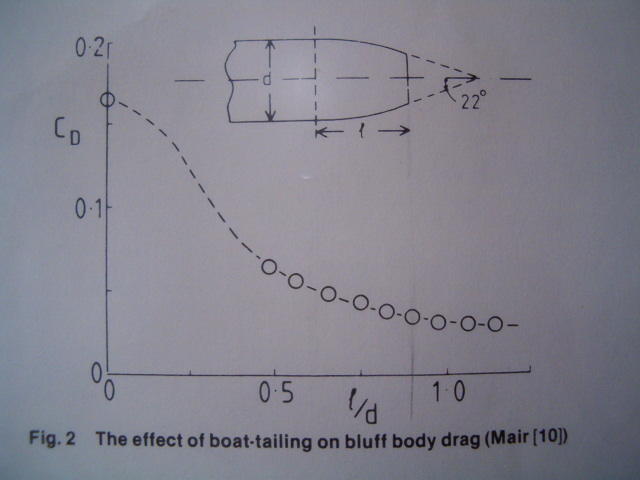
5) If you're doing a 'curved' boat-tail, then any tangent angle, at any point along the contour, will be a function of the location along the contour, as a percentage of the 'total' 100% tail. As Koenig-Fachsenfeld/ Kamm investigated at the FKFS, and W.A.Mair.
6) Technically, one would not exceed the degree of tapering seen on the aft-body of a streamline body of revolution, of 2.37:1 fineness ratio. This ratio was appropriate in the context of airship envelopes, of thousands of square-feet frontal area, where the turbulent boundary layer was so enormous that, the TBL sloughing off the rear, actually created 'phantom' tail surface.
7)As a scaredy-cat, I'm not comfortable recommending anything more aggressive than Mair's contour. It's basically what NASA used on their streamlining, except they exceeded 22-degrees beyond the 'natural' separation line, and the added stinger was embedded within turbulence, unable to provide any meaningful pressure recovery.
8) The particular2.37:1 contour WOULD exceed Mair's recommended 22-degree maximum for any part of the tail.
9) And using Mair's 22-degrees is 100% predicated upon using Mair's 'lead-in' contour to 22-degrees. Top and sides would have identical contour.
10) The 'diffuser' needs to respect the SAE' 10-degree 'departure' angle at a minimum, so as not to be shorn away ascending or descending ramps. A hinged, 'moveable' bottom section could get around clearance issues.
--------------------------------------------------------------------------------------
11) A fairing can be added to exposed axles. I've done this on Viking. The lowest drag is with a 4:1 aspect ratio symmetrical section enclosing the axle.
__________________
Photobucket album: http://s1271.photobucket.com/albums/jj622/aerohead2/
|
|
|
|
|
The Following User Says Thank You to aerohead For This Useful Post:
|
|
|
06-21-2022, 09:14 PM
|
#68 (permalink)
|
|
EcoModding DIY aer.or
Join Date: Oct 2020
Location: Virginia City, NV
Posts: 82
Thanks: 93
Thanked 69 Times in 57 Posts
|
Quote:
Originally Posted by aerohead
1) Three different researchers reported optimum drag reduction only with a 'long' diffuser of 'small' upsweep angle ( around 2.8-degrees )
2) Drag reduction for a 'short' diffuser occurred at a 4-degree upsweep.
3) W.H. Hucho mentions A.R. George's research of high underbody angles from June 18-20 ASME-CSME- Conference, 1979. These steep angles induced a counter-rotating pair of vortices, which induced an upwash, as a prismatic fastback would create a 'downwash'. If the vehicle already had an upper set of counter-rotating vortices, the lower set could be tuned to mitigate some of the vortex drag of the uppers. Any vorticity kills any chance of pressure recovery. It all becomes heat. Softened edges as on Orbywan's boat tail will prevent vortex formation in the first place, according to Carver-Funderburk at Texas Tech University.
----------------------------------------------------------------------------------
4) As to 'angles', they're completely contextual. If you're doing a simple angle, then, the 'optimum' angle will be a function of the proportion of the length of the tail, in comparison to the overall length of the vehicle. A percentage.
5) If you're doing a 'curved' boat-tail, then any tangent angle, at any point along the contour, will be a function of the location along the contour, as a percentage of the 'total' 100% tail. As Koenig-Fachsenfeld/ Kamm investigated at the FKFS, and W.A.Mair.
6) Technically, one would not exceed the degree of tapering seen on the aft-body of a streamline body of revolution, of 2.37:1 fineness ratio. This ratio was appropriate in the context of airship envelopes, of thousands of square-feet frontal area, where the turbulent boundary layer was so enormous that, the TBL sloughing off the rear, actually created 'phantom' tail surface.
7)As a scaredy-cat, I'm not comfortable recommending anything more aggressive than Mair's contour. It's basically what NASA used on their streamlining, except they exceeded 22-degrees beyond the 'natural' separation line, and the added stinger was embedded within turbulence, unable to provide any meaningful pressure recovery.
8) The particular2.37:1 contour WOULD exceed Mair's recommended 22-degree maximum for any part of the tail.
9) And using Mair's 22-degrees is 100% predicated upon using Mair's 'lead-in' contour to 22-degrees. Top and sides would have identical contour.
10) The 'diffuser' needs to respect the SAE' 10-degree 'departure' angle at a minimum, so as not to be shorn away ascending or descending ramps. A hinged, 'moveable' bottom section could get around clearance issues.
--------------------------------------------------------------------------------------
11) A fairing can be added to exposed axles. I've done this on Viking. The lowest drag is with a 4:1 aspect ratio symmetrical section enclosing the axle.
|
Good stuff ...thanks
1-3)Considering the length of the "tail"(axle to bumper) of this MH...even with the fuel tank back there... I can see a 2.8-degree diffuser in my future.
4) LOL...the angle verses tangent is all fun conversation
5-6) a curved boattail would likely be inflatable... which I'm struggling with - backing into campsites(seeing where I'm going), ladder, etc obstacles to usability. I'm not giving up here yet.
7+) limitations are important. The "rocketail" or a version of it(yes there is a patent), still appeals to me. 11 degrees of the 1st surface, 14 degrees of the 2nd. & only 27" long. connecting the "corners" would be a creation... almost artsy.
Is there somewhere I can get the 2.37:1 fineness ratio definition clearly? of course I'm not shortening the MH ...only adding(something store-able)to the rear.
11)A smoooth belly pan, including axle & pumpkin fairing I know I can resolve.
In other threads I see concern with coroplastic, it seems many use it with success & others have worry of longevity. |
|
|
|
|
The Following 2 Users Say Thank You to sregord For This Useful Post:
|
|
|
06-21-2022, 10:25 PM
|
#69 (permalink)
|
|
Master EcoModder
Join Date: Aug 2012
Location: northwest of normal
Posts: 29,413
Thanks: 8,367
Thanked 9,125 Times in 7,534 Posts
|
Quote:
|
connecting the "corners" would be a creation... almost artsy.
|
Four quadrilateral flaps and the corners filled with cone-shaped inflatables?
 https://i.pinimg.com/originals/88/2e...73ada468a4.jpg
IIRC, fineness ratio is for the compound curve Template. With torpedoes or truck vans, once you exceed a length where the disruptions at the front have found reattachment, it's all the same. See Mair.
If your d is 7-8ft, a 36" box cavity would be minimal.
__________________
.
.Without freedom of speech we wouldn't know who all the idiots are. -- anonymous poster
___________________
.
.tragectory: Line goes down and to the right.
Last edited by freebeard; 06-21-2022 at 10:31 PM..
|
|
|
|
|
The Following 2 Users Say Thank You to freebeard For This Useful Post:
|
|
|
06-23-2022, 10:53 AM
|
#70 (permalink)
|
|
Master EcoModder
Join Date: Jan 2008
Location: Sanger,Texas,U.S.A.
Posts: 16,534
Thanks: 24,520
Thanked 7,436 Times in 4,817 Posts
|
2.37:1 fineness ratio
I've never seen the actual 2.37 ratio streamline body of revolution referred to published.
If you go further back to Sighard Hoerner's 1951 edition of 'AERODYNAMIC DRAG', he reports the drag minimum @ 2.1:1. however, later in the book he reports that you wouldn't want to actually use it, and he doesn't provide a context.
These streamline bodies of revolution were originally intended for airship bodies.
--------------------------------------------------------------------------------------
When you study airships, you discover that, due to their enormous frontal areas, and wetted surface areas, that when their enormous turbulent boundary layers slough off their aft-bodies, the free-stream passes over the traveling TBL, attached to the tail, as if it's a phantom surface, actually modifying the 'apparent/ effective' fineness ratio.
This wouldn't happen on a passenger car. You could calculate the thickness of the TBL on the motorhome and think about it.
Another thing about airships is that, air sickness is a big issue for crew and passengers. Longer, higher drag envelopes provide a better 'ride.'
In military applications, the longer form provides a more stable weapons platform, especially with bombing.
--------------------------------------------------------------------------------------
Elliptical bodies have the same Cd/per fineness ratio as streamline bodies of revolution.
If you can get access to Wolf H. Hucho's 2nd-Edition book, on page 200, Figure 4.119, you'll see the drag minimum occurring @ 2.5: fineness ratio.
------------------------------------------------------------------------------------
On page 61 of the same book, Table 2.1, 3rd image from the bottom, you'll see a 'Streamlined body l/D = 2.5:1, @ Cd 0.04.
This body's aft-body does not exceed a declination angle which exceeds 22-degrees, W. A. Mair's minimum for attached flow.
In ground proximity, the body in ground reflection would be Cd 0.08. Around Cd 0.13 with wheels. This is what I used for one of the 'templates.'
--------------------------------------------------------------------------------------
I suspect that, anyone with AUTOCAD, could import a scan on Huchos' 2.5:1 body ( it's actually Hoerner's ) and 'shrink' it with the software, producing something close to a mathematically-correct 2.37:1 body. It would be way out ahead of nothing.
-----------------------------------------------------------------------------------
I'm a scaredy-cat when it comes to other people's time and finances when it comes to fabricating.
I've shied away from any contour which exceeds Mair's 22-degree threshold.
Some production contours do exceed 22-degrees. The ' Champrius' is an example. The 2008 Prius conforms to no known contour, however, if you follow a pathway, halfway through the rear spoiler, then it's an exact match for Wolfgang Klemperer's, 1922, Cd 0.15 streamline half-body.
The Prius aft-body constitutes 40.5% of total body length.
Without the spoiler, the rear separation point is @ a 16.5-degree angle to the horizon.
With the spoiler, it's relaxed to 13.5-degrees.
Halfway through the 3.5' spoiler extension, it's right on Klemperer's contour.
In order to reach Klemperer's 'long-tail' body, one would have to elongate the Prius by 2287.25mm ( 90" ).
------------------------------------------------------------------------------------
Perhaps someone with AUTOCAD can step up, and do the image morphing.
I'd like to see it myself.
__________________
Photobucket album: http://s1271.photobucket.com/albums/jj622/aerohead2/
|
|
|
|
|
The Following User Says Thank You to aerohead For This Useful Post:
|
|
|