06-08-2021, 09:37 PM
|
#561 (permalink)
|
|
Master EcoModder
Join Date: Aug 2012
Location: northwest of normal
Posts: 29,418
Thanks: 8,368
Thanked 9,128 Times in 7,537 Posts
|
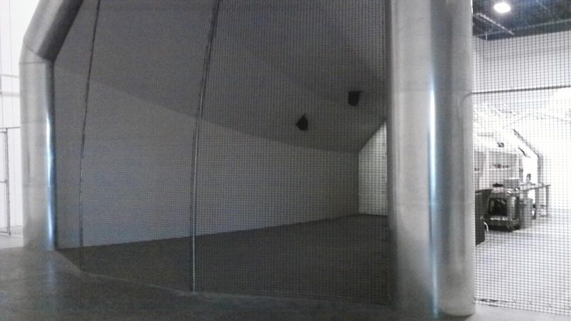
I know in the Darko wind tunnel they put a metal mesh upstream that affected the attachment through the throat.
__________________
.
.Without freedom of speech we wouldn't know who all the idiots are. -- anonymous poster
___________________
.
.tragectory: Line goes down and to the right.
|
|
|

|
|
The Following User Says Thank You to freebeard For This Useful Post:
|
|
 Today Today
|
|
|
|
 Other popular topics in this forum...
|
|
|
|
|
06-09-2021, 01:59 PM
|
#562 (permalink)
|
|
Master EcoModder
Join Date: Jan 2008
Location: Sanger,Texas,U.S.A.
Posts: 16,534
Thanks: 24,520
Thanked 7,438 Times in 4,818 Posts
|
what works
Quote:
Originally Posted by freebeard

There's got to be a line somewhere between what works and what doesn't. So -- 1/4 to 1/5th for air and 1/8th for water?
|
If anyone here has Hucho with them, he made a comment regarding the development of the Vanagon.
Minimum leading edge radii required to guarantee attached forebody flow on the scale model were found to be excessively large when in full-scale, even though they had the Reynolds number dynamic similarity covered.
__________________
Photobucket album: http://s1271.photobucket.com/albums/jj622/aerohead2/
|
|
|
|
|
The Following User Says Thank You to aerohead For This Useful Post:
|
|
|
06-09-2021, 02:02 PM
|
#563 (permalink)
|
|
Master EcoModder
Join Date: Jan 2008
Location: Sanger,Texas,U.S.A.
Posts: 16,534
Thanks: 24,520
Thanked 7,438 Times in 4,818 Posts
|
mesh
Quote:
Originally Posted by freebeard
I know in the Darko wind tunnel they put a metal mesh upstream that affected the attachment through the throat.
|
My thought is that, the mesh was just there to protect the flow-straightener egg-crate from damage, should some random jetsam get in there.
__________________
Photobucket album: http://s1271.photobucket.com/albums/jj622/aerohead2/
|
|
|
|
|
06-09-2021, 06:30 PM
|
#564 (permalink)
|
|
Master EcoModder
Join Date: Aug 2012
Location: northwest of normal
Posts: 29,418
Thanks: 8,368
Thanked 9,128 Times in 7,537 Posts
|
The guy running it said some thing about attached turbulence in the test section before they added it.
__________________
.
.Without freedom of speech we wouldn't know who all the idiots are. -- anonymous poster
___________________
.
.tragectory: Line goes down and to the right.
|
|
|
|
|
The Following User Says Thank You to freebeard For This Useful Post:
|
|
|
06-11-2021, 10:05 AM
|
#565 (permalink)
|
|
Master EcoModder
Join Date: Jan 2008
Location: Sanger,Texas,U.S.A.
Posts: 16,534
Thanks: 24,520
Thanked 7,438 Times in 4,818 Posts
|
before they added it
Quote:
Originally Posted by freebeard
The guy running it said some thing about attached turbulence in the test section before they added it.
|
Seems like any turbulence attributed to the screen would be insignificant compared to the turbulence created within the deep, egg-crate flow straightener at the jet.
Gary Eaker could probably tell us about that.
__________________
Photobucket album: http://s1271.photobucket.com/albums/jj622/aerohead2/
|
|
|
|
|
06-11-2021, 10:31 AM
|
#566 (permalink)
|
|
Master EcoModder
Join Date: Jan 2008
Location: Sanger,Texas,U.S.A.
Posts: 16,534
Thanks: 24,520
Thanked 7,438 Times in 4,818 Posts
|
about scale models.......................
I went back through Hucho.
What I was remembering, turned out to be about the 1951 VW microbus, compared to the 1969 Vanagon.
Pawlowski published on minimum leading edge radii requirements in 1930.
Lay's research in 1933 confirmed the efficacy of Pawlowski's work.
M'o'ller, in 1951, did not use Pawlowski's geometry for the VW bus.
It turned out that, the 1951 design would have had no greater drag, if the front radii had been just a fraction of what was used.
--------------------------------------------------------------------------------------
With respect to scale models:
Hucho suggests that anything below 1/4-scale would be good only for 'qualitative' investigation. You would not be able to do 'quantitative' work below that 'size'.
In the United States, the typical minimum model scale is 3/8ths, as of 1986.
Hucho said that 1/4-scale results are identical to 1:1-scale.
In 1991, Texas Tech University was using 1/24-scale in their small water tunnel, for food coloring-injected flow imaging. Only.
For underwater tow-testing and actual drag measurements from an overhead gantry bridge- supported sting, they used a 3/8-scale model, and SCUBA divers for close observation and image capture.
Ford paid $ 68,000 for a highly accurate 3/8-scale Ford Taurus model, with clear plastic hood ( bonnet ), complete with all engine bay structures, to develop CFD code. Model velocity was 2-mph.
__________________
Photobucket album: http://s1271.photobucket.com/albums/jj622/aerohead2/
|
|
|
|
|
The Following 2 Users Say Thank You to aerohead For This Useful Post:
|
|
|
06-20-2021, 12:48 PM
|
#567 (permalink)
|
|
EcoModding Lurker
Join Date: Jan 2021
Location: Ontario, Canada
Posts: 68
Thanks: 54
Thanked 50 Times in 35 Posts
|
Tapes are just to give visualization where a tailgate split could be vs. how side wall would blend in.... tape measure is probably closer to a shape planned (from sideview)....
|
|
|
|
|
06-20-2021, 01:18 PM
|
#568 (permalink)
|
|
Cyborg ECU
Join Date: Mar 2011
Location: Coastal Southern California
Posts: 6,302
Thanks: 2,374
Thanked 2,176 Times in 1,471 Posts
|


In the second image, I think the tape measure line might be at a too-steep angle in the aft portion and could produce separation sooner than you'd prefer. Do you have the means to build a prototype, possibly of cardboard for tuft testing? You could build it, tuft test it, modify it, tuft test it, and by that means get a better sense of the most likely shape.
__________________
See my car's mod & maintenance thread and my electric bicycle's thread for ongoing projects. I will rebuild Black and Green over decades as parts die, until it becomes a different car of roughly the same shape and color. My minimum fuel economy goal is 55 mpg while averaging posted speed limits. I generally top 60 mpg. See also my Honda manual transmission specs thread.


|
|
|
|
|
06-20-2021, 01:33 PM
|
#569 (permalink)
|
|
Master EcoModder
Join Date: Aug 2012
Location: northwest of normal
Posts: 29,418
Thanks: 8,368
Thanked 9,128 Times in 7,537 Posts
|
I would have gone with 'the left and right don't match'.
I also see something that arcs from the separation line on the back of the cab into a plastic crate on the tailgate. Possibly to hold the arc line?
I would consider the Camper World race truck spoilers. And other aerocaps that have a flat truncation about half their height.
 https://www.nascar.com/wp-content/up...in-625x340.jpg
Another example:
...and an L-shaped hatch like the Dodge Magnum for access to the bed.
__________________
.
.Without freedom of speech we wouldn't know who all the idiots are. -- anonymous poster
___________________
.
.tragectory: Line goes down and to the right.
Last edited by freebeard; 06-20-2021 at 01:38 PM..
|
|
|
|
|
06-20-2021, 01:59 PM
|
#570 (permalink)
|
|
EcoModding Lurker
Join Date: Jan 2021
Location: Ontario, Canada
Posts: 68
Thanks: 54
Thanked 50 Times in 35 Posts
|
Lol... the plastic milk box was simply to hold the tape measure in place... The arc, formed by tape measure is just to visualize that the cap will not be straight (as the tapes are). Prototype of the cap with detachable extension is under planning.... with tuff test and ABA tests... these are just initial captures of the cap idea.
I have traced trucks cabin exterior shape and extrapolated it and surprisingly, an arch goes pretty close to end of the trucks bed... the extension piece will be made exactly same arch as the cabin and the cap....
|
|
|
|
|