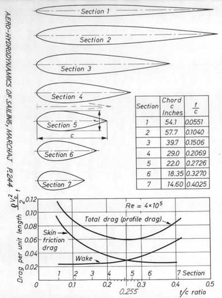
The question I have with your dark red is that it is scaled to the size of the vehicle. I think that as long as we're talking about largish objects like cars, trucks, boats & motorcycles, the 115° flow separation rule applies. So as long as we keep our top radius line from going past that 115° point, it really doesn't matter the shape. The reason we use this particular template is that it has the best "surface area/ wake generation" ratio. The segment we use is very similar to section 5.
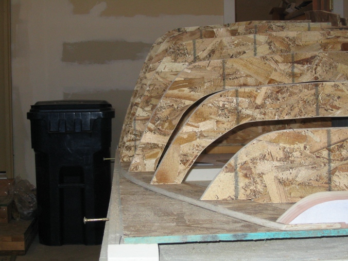
This brings up another point that I think people don't often consider. We spend a lot of time trying to make the tops of our vehicles as aero as possible, and often neglect the sides. The air moving around the sides of our trucks and cars has a large impact as well I say. On my Pickup, the sides are about 22" tall on the passenger cabin, just in front of the bed. The roof width at the top in this area is about 52" so with 2 sides at 22", that's 44" of air surface. So we worry about 55% of the equation and neglect the other 45%. This is why I have designed a taper in the sides of my aerocap when viewed from the top. Doing this results in a fastback design.
More food for thought....It is often said that the best possible Cd we can achieve is .18 based on the .09 holy grail of aero shape in ground effect...The sides of the vehicle are not in ground effect. Hmmmmmmmmmm.
Forum search "2.5:1 fineness ratio" and read what Aerohead has posted in other threads.
Aerohead would be best to respond on that but I think what you've talking about is similar to what the GM EV1 had at the rear. The back of that exceeded the template angle but still had a .19 Cd. That vehicle also curves in on the sides similar to your cap.
This brings up another point that I think people don't often consider. We spend a lot of time trying to make the tops of our vehicles as aero as possible, and often neglect the sides. The air moving around the sides of our trucks and cars has a large impact as well I say. On my Pickup, the sides are about 22" tall on the passenger cabin, just in front of the bed. The roof width at the top in this area is about 52" so with 2 sides at 22", that's 44" of air surface. So we worry about 55% of the equation and neglect the other 45%. This is why I have designed a taper in the sides of my aerocap when viewed from the top. Doing this results in a fastback design.
I agree. Look at most trucks' head-on silhouette. Height is comparable to width. But there are two sides to go around and only one top to go over. So my bet is more air pushes around the two sides combined than goes over. Sure some goes under too but that has to be the least given the road constraint. I think side profile analysis (top and bottom flow) is less than half the total. Top view analysis (flow on both sides) cannot be neglected on a truck if the real goal is optimizing in 3D. Cars? Maybe...
You state somewhere in here that the wheels of the vehicle should rest on the ground plane.
Yet you say that flow separation occurs at 4 seconds after midnight.
It seems to me that these 2 statements contradict in the sense that air will either remain attached to a given shape until it reaches 4 seconds past midnight (115° beyond stagnation) on a curve (Red), or, you need to overlay a huge wing section onto a given vehicle (Green), and if you fall below this line at any point, you have flow separation, even if it occurs at some point less than 115° (which in this case is on the ground 20 feet behind the truck).
Which one is it? Red or Green? Or am I missing something? (Again, as usual)
(1) Yes,the longitudinal centerline constitutes the ground plane and the vehicle would be scaled to fit with it's wheels on the "ground",and the highest point of the roof aligned with the 12:00 O'clock position.The rest of the roofline is defined by the curve.
(2) The very back of the teardrop is the separation point,so all points ahead of that are in attached flow.
(3) Since all vehicles must have ground clearance,it would be impossible(and unnecessary ) to build a body the full length of the drop,as it would end where intersected by the belly line.
Al is closing the store,I've got to close now,will catch up asap.
I agree. Look at most trucks' head-on silhouette. Height is comparable to width. But there are two sides to go around and only one top to go over. So my bet is more air pushes around the two sides combined than goes over. Sure some goes under too but that has to be the least given the road constraint. I think side profile analysis (top and bottom flow) is less than half the total. Top view analysis (flow on both sides) cannot be neglected on a truck if the real goal is optimizing in 3D. Cars? Maybe...
My 2c
KB
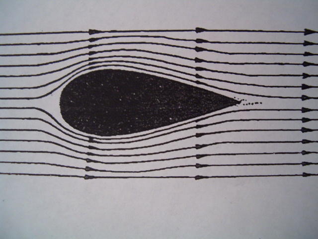
Even in cars, side flow interferes greatly with top flow. The effect can be noted in a wind tunnel with multiple smoke streams, where one will suddenly diverge from it's "apparent" path. Without seeing all the other flow lines, one might not be able to explain this, but having seen the "rest of the equation", so to speak, one can then understand that flow does not necessarily proceed in a straight curve or an "apparent" arc over or around an object in a fluid.
I think that many of us fall victim to looking at profile flow as opposed to plan view because some of the most aerodynamic vehicles appear to pay specific attention to profile. I think we neglect to notice that their profiles are also much, much smaller than even our smallest cars.
Since lift can occur in any vector, (you change it's name to understand directionality, but the force remains the same) side flow is just as important, if not moreso, since it represents 2/3 of the exposed aerodynamics equation (roughly).
I gotta be honest here; I'm not entirely sure I understand exactly what is going on in your mind with this one.
I'm desperately trying to follow, but from what I can tell, your pattern (it's yours, right?) suggests that for attached flow, we'd need something along the lines of a 30 foot long vehicle with a bull nose, which doesn't seem to follow the logic of a 3:1 relationship between length and frontal area.
Could I trouble you to elaborate a bit more?
EDIT: I think I understand a little bit better, after having re-read the text and taking a more detailed look at the images. I do, however, still have a question - since the profile of the divine shape is a curve, at what point do we measure the angle of descent?
I notice in your image that it states a 22* angle at approximately 1/4 of the distance from the tail tip to the "12 o'clock", or the area at which cross sectional diameter is the largest. Is that the proper measurement there, or do we average the slope of the full form against the flat center line?
Also - does this apply as is to a land-vehicle, when given the ground effect?
MJ, I am using exactly what Aerohed described. I have analyzed the shape you posted here and have the results below. I hope it makes sense.
In this image I have placed your teardrop ideal and the ideal that Aerohed presented earlier. Your shape is the bright green one in this image. My shape is red. I have been extremely careful not to mess with any of the proportions of these shapes at anytime. Also, I have made a circle in my drawing program and have marked a point which is 25° past center and then I trace this shape to get my template, I did not simply trace Aeroheds foil shape.
In this image I have overlaid my shape (bright green) with the foil cross sections which I got from somewhere. You can see that my shape closely approximates the shape # 5 on this chart, your shape (red) is pretty close to #7.
I have noticed that the nose shapes on Aeroheds foil, your template, your ideal foil, and these foils on the chart are all quite different. This I suppose could be the subject of a new discussion.
The Following User Says Thank You to ChazInMT For This Useful Post:


") Hmmmmmmmmmm.
Hmmmmmmmmmm.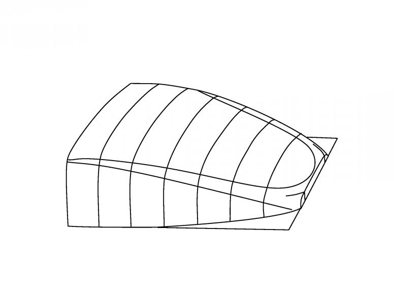

 Today
Today