 04-09-2016, 02:45 PM
|
#11 (permalink)
|
|
...beats walking...
Join Date: Jul 2009
Location: .
Posts: 6,190
Thanks: 179
Thanked 1,525 Times in 1,126 Posts
|
This picture clearly illustrates a "perfect" crimp. See how uniform the copper material appears, with absolutely NO demarcation between the crimp itself and the copper strands, giving the visual appearance of being "one" solid piece of copper:

|
|
|

|
 Today Today
|
|
|
|
 Other popular topics in this forum...
|
|
|
|
 04-09-2016, 04:28 PM
|
#12 (permalink)
|
|
EcoModding Apprentice
Join Date: Feb 2015
Location: Sacramento
Posts: 202
Thanks: 3
Thanked 225 Times in 91 Posts
|
My BMS is an Orion. When I first bought it, I was still back in the frame of mind where a bms is just a piece of equipment that kept the pack top balanced, and had some high and low voltage cut offs. It took me a couple builds to fully grasp what an Orion does, but I am hooked now.
I have tried other crimp shapes, but have not done 8 sides. I messed with 6 sides, but it does not work the way I like with only one linear plane where the dies slide together. I have also done a mirror image of what I posted above on the bottom side as well so that there are two anvil indentations across from each other. The deeper crimp that I posted works out best, and the sides of the crimp actually get squeezed in a little as the anvil forces the terminal to the bottom of the receiving portion, since I made the bottom receiver of my tool have a very slight v shape.
|
|
|

|
 04-09-2016, 04:31 PM
|
#13 (permalink)
|
|
EcoModding Apprentice
Join Date: Feb 2015
Location: Sacramento
Posts: 202
Thanks: 3
Thanked 225 Times in 91 Posts
|
Quote:
Originally Posted by Old Tele man

This picture clearly illustrates a "perfect" crimp. See how uniform the copper material appears, with absolutely NO demarcation between the crimp itself and the copper strands, giving the visual appearance of being "one" solid piece of copper:
 |
That crimp tests very nicely under load, but you can see the line across the terminal where the anvil mark does not transition as well as it should. It risks shearing strands.
|
|
|

|
 04-09-2016, 09:04 PM
|
#14 (permalink)
|
|
Corporate imperialist
Join Date: Jul 2011
Location: NewMexico (USA)
Posts: 11,312
Thanks: 273
Thanked 3,584 Times in 2,845 Posts
|
Most of the high power variable frequency drives I work with use a crimp that crimps like that, making a triangular or kind of a chevron shape crimp.
__________________
1984 chevy suburban, custom made 6.5L diesel turbocharged with a Garrett T76 and Holset HE351VE, 22:1 compression 13psi of intercooled boost.
1989 firebird mostly stock. Aside from the 6-speed manual trans, corvette gen 5 front brakes, 1LE drive shaft, 4th Gen disc brake fbody rear end.
2011 leaf SL, white, portable 240v CHAdeMO, trailer hitch, new batt as of 2014.
|
|
|

|
 04-10-2016, 12:58 AM
|
#15 (permalink)
|
|
Master EcoModder
Join Date: Sep 2010
Location: Saskatoon, canada
Posts: 1,488
Thanks: 746
Thanked 565 Times in 447 Posts
|
Quote:
Originally Posted by oil pan 4

Most of the high power variable frequency drives I work with use a crimp that crimps like that, making a triangular or kind of a chevron shape crimp.
|
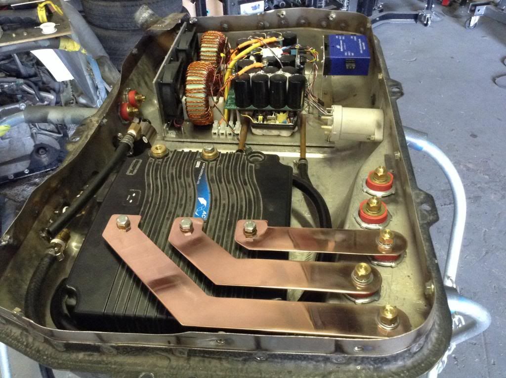
That's a good point .. I should look at what our vendors are doing for their crimps on VFDs. I know that at least one of them is using copper buss bar instead of cabling inside the power section. They can bend the buss much sharper than they can bend cables. Plus the buss is bolted to insulators, so it does not move around or rub against other cables, edges, etc during high current events.
But I have not paid much attention to what they've done with the crimps on the cables that they still use. |
|
|

|
 04-10-2016, 12:12 PM
|
#16 (permalink)
|
|
EcoModding Apprentice
Join Date: Feb 2015
Location: Sacramento
Posts: 202
Thanks: 3
Thanked 225 Times in 91 Posts
|
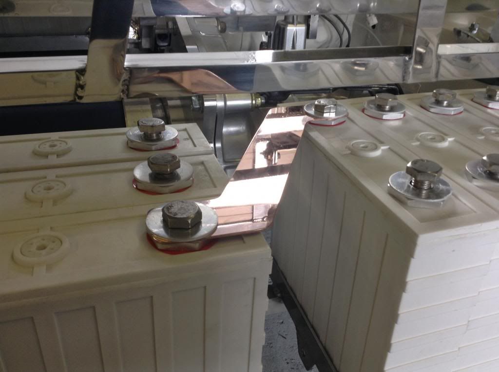
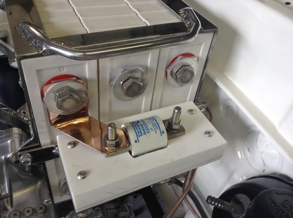
The use of bus bars wherever possible is best, since half as many mating surfaces compared to crimp cables. Cables have strand to crimp lug contact, plus crimp lug to terminal, bus bars only have bar to terminal. I like to use bars, even in places where cable could be used.


Cable would have been tight here. The bus bar is cut to maximize the surface of the fuse though.

. |
|
|

|
|
The Following User Says Thank You to EVmetro For This Useful Post:
|
|
 04-10-2016, 02:26 PM
|
#17 (permalink)
|
|
Corporate imperialist
Join Date: Jul 2011
Location: NewMexico (USA)
Posts: 11,312
Thanks: 273
Thanked 3,584 Times in 2,845 Posts
|
The military seems to like to silver plated hardware.
__________________
1984 chevy suburban, custom made 6.5L diesel turbocharged with a Garrett T76 and Holset HE351VE, 22:1 compression 13psi of intercooled boost.
1989 firebird mostly stock. Aside from the 6-speed manual trans, corvette gen 5 front brakes, 1LE drive shaft, 4th Gen disc brake fbody rear end.
2011 leaf SL, white, portable 240v CHAdeMO, trailer hitch, new batt as of 2014.
|
|
|

|
 04-12-2016, 12:47 PM
|
#18 (permalink)
|
|
Corporate imperialist
Join Date: Jul 2011
Location: NewMexico (USA)
Posts: 11,312
Thanks: 273
Thanked 3,584 Times in 2,845 Posts
|
All the big VFDs use aluminum buss bars.
I think the ultimate efficiency would be copper buss bars that have been silver plated.
The crimps used by allen Bradley in the big drives look a lot like, if not identical to what you have there.
__________________
1984 chevy suburban, custom made 6.5L diesel turbocharged with a Garrett T76 and Holset HE351VE, 22:1 compression 13psi of intercooled boost.
1989 firebird mostly stock. Aside from the 6-speed manual trans, corvette gen 5 front brakes, 1LE drive shaft, 4th Gen disc brake fbody rear end.
2011 leaf SL, white, portable 240v CHAdeMO, trailer hitch, new batt as of 2014.
|
|
|

|
 04-13-2016, 10:53 PM
|
#19 (permalink)
|
|
Master EcoModder
Join Date: Sep 2010
Location: Saskatoon, canada
Posts: 1,488
Thanks: 746
Thanked 565 Times in 447 Posts
|
A crimp on a 350 amp VFD
An example crimp on one of our older Siemens VFDs
Rated 354 amps continuous at 575VAC
The first pic is of the 3 phases off the bottom of the output bus. Second picture is a close-up of the crimp.
https://www.flickr.com/photos/141097.../shares/yos295
It looks a lot like EVMetro's cut-away
What did you use to slice through the crimp so cleanly? I will attempt to cut a couple of crimps apart to see how good they were. |
|
|

|
 04-13-2016, 11:02 PM
|
#20 (permalink)
|
|
Master EcoModder
Join Date: Sep 2010
Location: Saskatoon, canada
Posts: 1,488
Thanks: 746
Thanked 565 Times in 447 Posts
|
Another example, 600 amp at 575V
2 more pictures with longer lugs and 2 bolts per lug to the phase bus
The crimp-on connectors are longer and the circular crimp does not begin on the edge, but about 1/4 of an inch in. It also stops about 1/4 of an inch from the edge.
https://www.flickr.com/photos/141097.../shares/Xc261q
|
|
|

|
|