09-24-2008, 09:46 PM
|
#1 (permalink)
|
|
EcoModding Lurker
Join Date: Apr 2008
Location: Georgetown, KY
Posts: 23
Thanks: 0
Thanked 1 Time in 1 Post
|
 Internal aerodynamics
OK... so here's an obtuse way to think about aerodynamics.
On my truck (Chevy Silverado w/Duramax diesel), it has been discovered that the stock air intake, especially where the incoming air makes the final 12-18 inches into the turbocharger, is quite restrictive. This discovery, and the discovery that in later years GM re-engineered the turbo mouthpiece to be much less restrictive (so much so that mileage, power, and engine temps are all noticeably affected - all to the positive), has all of my diesel brethren scrambling to modify their trucks - OK... I did too.
The difference is startling, especially under acceleration, towing, etc. At highway speeds, unless you're towing, the turbo clearly has all the air it needs as boost is 2-5 psi; under load, it's not uncommon to see it in the 24-30 psi, which is where you really notice the difference with this mod.
Now my questions. How would one quantify the optimal solution? Realizing that you have to pull air through a filter, and given a predictable turbo flow rate (none of which I can personally quantify ") ), I'm wondering how one would go about validating/verifying a solution.
For example, all of these intake systems have an accordion-like rubber section that attach both to the filter box and the rigid pieces of the intake which leads to the turbo (it allows you to open up the filter box to change the filter). Does the accordion significantly disrupt airflow? Would it be measurable? If the accordion isn't straight, would that affect anything?
Then there's this other guy out there who claims that for an optimal solution, you must profile the interior of the air intake system and dimple it like the surface of a golf ball... and he claims the solution he sells has this feature. Is this primarily theoretical, real but hard to imagine it would be noticed, all hooey, or [fill-in-the-blank]?
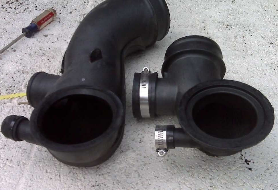
I'd be interested to hear your thoughts... BTW, here are some pics to demonstrate the differences in the turbo mouthpiece alone - the smaller one is the stock mp from the LLY engine; the larger one is from the next generation LBZ engine.
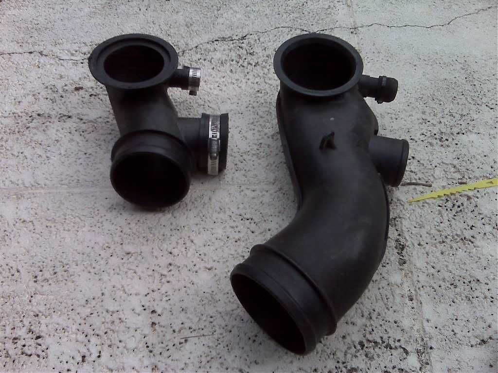
This is the turbo side end of the mp:
__________________
Randy
Just your average 7,000 lb 4-wheel drive 22 mpg eco modder...  "Suppose I were a congressman. And suppose I were an idiot. But I repeat myself..."
 - Mark Twain
Last edited by Randy_the_Hack; 09-24-2008 at 09:57 PM..
|
|
|

|
 Today Today
|
|
|
|
 Other popular topics in this forum...
|
|
|
|
|
09-25-2008, 09:53 AM
|
#2 (permalink)
|
|
Master EcoModder
Join Date: Jul 2008
Location: Tallmadge, OH
Posts: 313
Thanks: 6
Thanked 26 Times in 21 Posts
|
I'm not an engineer (never even owned a train), but here's my take. At any given rpm your engine needs X amount of oxygen. The easier it is to get it, the less power it will take from the engine. The flow of air around the edges of the intake tube is slower than in the middle. Dimples will help that if the air is moving faster than about 75mph. They will hurt it at slower speeds.
My Conclusion: There is a point of diminishing returns in tricking out your intake--as well as any other mod. Usually, I've found that mods not too far from stock are way to go. If you've got enough flow now, why do you need more?
|
|
|
|
|
09-25-2008, 10:57 AM
|
#3 (permalink)
|
|
EcoModding Lurker
Join Date: Jan 2008
Location: Sydney, Australia
Posts: 76
Thanks: 1
Thanked 3 Times in 3 Posts
|
The Golf Ball dimples are an example of a good idea taken out of context. The dimples are there to keep the flow around the golf ball from separating, on the inside of a tube that is not really a problem. That product sounds like a huge gimmick.
If you want a scientific way to measure the intake restriction have a look at this autospeed article. If that doesn't help just search the website for other articles on air intakes. They have a 3 part series called into the intake:- for FE focus on the mods which reduce flow restriction rather than the cold air intake stuff. |
|
|
|
|
09-25-2008, 11:58 AM
|
#4 (permalink)
|
|
Master EcoModder
Join Date: Jan 2008
Location: Mirabel, QC
Posts: 1,672
Thanks: 35
Thanked 86 Times in 57 Posts
|
Autospeed is definitely your friend. You just have to measure the pressure drop across various components of your intake.
The only place I could possibly see dimples doing something would be on the inside of a sharp bend, maybe, given the right circumstances.
|
|
|
|
|
09-25-2008, 12:57 PM
|
#5 (permalink)
|
|
Master EcoModder
Join Date: Feb 2008
Location: West Coast, USA
Posts: 516
Thanks: 6
Thanked 78 Times in 57 Posts
|
To test, use or make a flow bench. Tightly seal your most powerful vacuum(s) available to the parts you want to test. Ensure the path leading to and from the part you want to test mimics the vehicle installation as much as possible to consider turbulence in those paths. Measure pressure in and out. Look up flow bench procedures, this is a tried and true means of measuring flow, and there is alot of knowledge and well documented methods and formulas for using them.
You could probably get a gross idea of flow differences by measuring deflection of a piece of card stock over the end of the exhaust from the shop vac, or measure the amperage draw of the vac.
OTOH, the improved stock part is probably pretty good unless you're using higher than normal boost or rpm, certainly outside typical hypermile driving cycles. Making further improvements is probably into the diminishing returns end of the $/benefit or time/benefit scale.
__________________
Good design is simple. Getting there isn't.
|
|
|
|
|
09-25-2008, 06:54 PM
|
#6 (permalink)
|
|
Master EcoModder
Join Date: Jan 2008
Location: Sanger,Texas,U.S.A.
Posts: 16,483
Thanks: 24,508
Thanked 7,436 Times in 4,817 Posts
|
Quote:
Originally Posted by Randy_the_Hack

OK... so here's an obtuse way to think about aerodynamics.
On my truck (Chevy Silverado w/Duramax diesel), it has been discovered that the stock air intake, especially where the incoming air makes the final 12-18 inches into the turbocharger, is quite restrictive. This discovery, and the discovery that in later years GM re-engineered the turbo mouthpiece to be much less restrictive (so much so that mileage, power, and engine temps are all noticeably affected - all to the positive), has all of my diesel brethren scrambling to modify their trucks - OK... I did too.
The difference is startling, especially under acceleration, towing, etc. At highway speeds, unless you're towing, the turbo clearly has all the air it needs as boost is 2-5 psi; under load, it's not uncommon to see it in the 24-30 psi, which is where you really notice the difference with this mod.
Now my questions. How would one quantify the optimal solution? Realizing that you have to pull air through a filter, and given a predictable turbo flow rate (none of which I can personally quantify ), I'm wondering how one would go about validating/verifying a solution.
For example, all of these intake systems have an accordion-like rubber section that attach both to the filter box and the rigid pieces of the intake which leads to the turbo (it allows you to open up the filter box to change the filter). Does the accordion significantly disrupt airflow? Would it be measurable? If the accordion isn't straight, would that affect anything?
Then there's this other guy out there who claims that for an optimal solution, you must profile the interior of the air intake system and dimple it like the surface of a golf ball... and he claims the solution he sells has this feature. Is this primarily theoretical, real but hard to imagine it would be noticed, all hooey, or [fill-in-the-blank]?
I'd be interested to hear your thoughts... BTW, here are some pics to demonstrate the differences in the turbo mouthpiece alone - the smaller one is the stock mp from the LLY engine; the larger one is from the next generation LBZ engine.
This is the turbo side end of the mp:
|
Randy,the only thing I can think to do for quantifying whats going on,is to add some static pressure taps before and after the components,and attach a u-tube or inclined manometer,or Magnehelic pressure gauge,and actually measure the pressure differentials,before and after the mods.This is what tuners will do with their flow-benches,and you can "read" the results directly.If you have a W.W.Grainger in your area,they'll have everything you'll need.---------------- As to the accordian snorkel hose.I don't think it impacts flow resistance at all.And with respect to the dimpling of the interior of the ductwork I would be very suspicious.I was an HVAC techie kind of engineer doing air balance all over the country,and my recollection is that,as with our cars,ductwork,even as small as your diesel's intake,is operating in a high Reynold's Number environment,with turbulent boundary layer,and dimpling would not improve on that.After passing the compressor section of the turbo,it wouldn't matter what had happened to the air before it got there.
__________________
Photobucket album: http://s1271.photobucket.com/albums/jj622/aerohead2/
|
|
|
|
|