11-21-2014, 09:32 PM
|
#41 (permalink)
|
|
EcoModding Apprentice
Join Date: Aug 2014
Location: Adelaide, Australia
Posts: 120
Thanks: 53
Thanked 54 Times in 33 Posts
|
I also found another interesting "formula" based calculator for header design here:
Pipe Sizing Calculator - this one is clearly a work in progress, but it's interesting because it implements a couple of alternative formulas from different sources for obtaining pipe lengths. All the methods which take into account RPM or mass flow (including the formula / calculator mentioned earlier) seem to be in fairly good agreeance on the basic parameters, so that's a positive sign 
Some other good insights from comparing the various formulae:
The calculator asked for aggregate exhaust valve diameter (i.e. how big a single valve of the same area would be) which turns out to be 36.75mm. Various sources agree that if the cross sectional areas of the primary pipe, exhaust valve and exhaust runner (inside the head) are approximately equal, you shouldn't loose much/any power at high RPMs unless the primaries are very long (i.e. friction losses). 1.5" OD SS pipe (with the 1.5mm wall thickness that seems to be pretty standard for exhaust systems - not "steam pipe" thickness though) has an internal diameter of 35.1, which seems pretty close... taking into account the valve stem area, it's an area reduction of only ~3%. Based on this I'm comfortable choosing 1.5" OD for the (first section of) the primaries.
Another interesting thing, backed up by some further reading, is that there seem to be three schools of thought regarding primary vs. secondary pipe length with tri-y / 4-2-1 headers. One school prefers equal length primary and secondary (based on 1/2 the total length to the final collector), another other prefers 15" all the time, and the third uses a length proportional to volume * exhaust stroke time. Funnily enough, in the 5000-6000 rpm range, all these numbers fall between about 13.5" and 15"  , so they're pretty similar for 'conventional' applications, and the differences would probably only change things by a couple of 100rpm at most. For lower RPMs, though, they're very different - the methods that take account of engine speed all spit out 31-33", while other methods not dependent on RPM spit out 14-15".
Using some more accurate valve timings (turns out the ones I found earlier were for an aftermarket cam), all the different formulae give distance to the final collector / reflection point as being in the 62"-72" range at 2400rpm. Based on this, I'm happy with putting the final Y at around 60" with the cat straight after to provide secondary reflections.
Based on this, I think I'll keep my original plan of an anti-reversion step at 14-15" to capture the first rarification pulse reflection (especially useful at high RPM), and a merge at 32"... between harmonics and the fact the the flow-rate-based formula and 1/2 total length rule agree on ~32", it can't be too terrible
As for simulation software, I've taken a closer look at discussion and screenshots of pipeMax, it looks like 'simulation' consists of outputting predicted torque/power curves rather than any actual FEA or similar code, and it's unclear whether you can 'simulate' an arbitrary connection of pipes rather than the generated selection. Given the price of 'real' simulation software, the "try it and see" method actually works out cheaper provided I go through 3 or less iterations of the design, and even then that's assuming each iteration is scratch-built from new stainless steel  ... and of course, getting the exact measurements will likely only shift things by a couple of 100rpm, which only matters for a highly tuned system (high Q-value resonance) and I'm thinking mild UEL (by about 10%) would be better for this application anyway, as it should give a smoother response.
Last edited by Madact; 11-22-2014 at 02:14 AM..
|
|
|

|
 Today Today
|
|
|
|
 Other popular topics in this forum...
|
|
|
|
|
11-22-2014, 03:40 AM
|
#42 (permalink)
|
|
EcoModding Lurker
Join Date: Nov 2014
Location: UK
Posts: 42
Thanks: 0
Thanked 12 Times in 12 Posts
|
Quote:
Originally Posted by Madact

Thanks Nigel_S, ever_green.
Unfortunately I don't have a lot of tuning options available to me - the ECUs supplied with Australian 6th gen Civics are either too primitive to update maps on, or just too small a market for tuning companies to make chips / add-on modules for. Whichever it is, as far as I can find out from internet forums and tuning kit manufacturer websites, the stock ECU is a black box as far as that's concerned. Now, one thing which I do have planned is a head swap using a D15Z7 head and ECU - same applies, it's an OBD2a ECU with no flashable memory, and I want to keep the stock ECU to correctly handle the 3-stage VTEC.
What I was planning there, given an ECU from a 1.5L engine on a 1.6L, was to carefully compare injector flow specs, and use an aftermarket adjustable fuel pressure regulator to increase the pressure 5-10% to keep the ECU within its parameters (especially in open loop mode) and keep the engine happy. On a side note, I went and spent money on parts before checking that theory ") - am I on the right track there?
Do you think the same would work (i.e. with no ECU tuning per se) in terms of tuning open-loop fuel flow for a non-stock header (assuming the ECU can handle closed-loop conditions correctly in my case)? I presume doing this properly would require use of a dyno and appropriate exhaust gas measurement? It works in my head, just not sure how it will go in practice |
A 5% increase in fuel pressure gives a very small increase in flow, not a 5% increase - look up the theory or an online calculator. If you need more than a few % extra fuel then consider swapping the injectors for higher flow ones. Adjusting fuel pressure is good for fine tuning if you can't change the map.
The ECU will have limits on its closed loop self tuning. If it is not using much self tuning from base to start with then your manifold will probably still have it within its limits but if there is something else it is having to adjust for then it could go beyond them. Some extra fuel pressure or higher flow injectors will bring it back towards the centre of its range allowing it to keep things perfect in closed loop.
To adjust it properly will require a session on a dyno but you can get close just by timing the acceleration from 1000rpm to 6000rpm in 3rd gear and adjusting the fuel pressure until you get the best time, then back it off a little since best economy comes with less fuel than best power and keep a watch on the tail pipe - if it collects carbon then it's got too much fuel pressure. If you are spending most time in closed loop rather than on a race track then that's probably close enough and you can't get exact anyway since the manifold will have different amounts of effect at different revs and to get that perfect needs a map change. |
|
|
|
|
The Following User Says Thank You to Nigel_S For This Useful Post:
|
|
|
11-22-2014, 04:47 AM
|
#43 (permalink)
|
|
EcoModding Lurker
Join Date: Nov 2014
Location: UK
Posts: 42
Thanks: 0
Thanked 12 Times in 12 Posts
|
Quote:
Originally Posted by Madact
Based on this, I think I'll keep my original plan of an anti-reversion step at 14-15" to capture the first rarification pulse reflection (especially useful at high RPM), and a merge at 32"... between harmonics and the fact the the flow-rate-based formula and 1/2 total length rule agree on ~32", it can't be too terrible |
I still think this is wrong. I've just had a look at the calculations I did when I changed my header and the result is 31.49 inches which agrees with your figures, however I'm using 16" primaries so why does practice not coincide with the calculations? The headers that are on sale tend to be either 16" primaries & 16" secondaries or 24" & 8" both designs giving 32" total, I've not come across 32" primaries for sale.
I think the reason is that almost all of the formulae documented on the web are for V8 engines while we have straight 4 engines which use a different firing order. The V8 calculations time the pulses for a cylinder which fires 360? degrees later but we need to time them for the other cylinder in the pair which fires 180 degrees later thus we want primaries half the length. Or something like that, I'm not too sure about the V8 firing orders and angles.
I do know that on my straight 4 engine, a tri-y header with 16" primaries give a substantial torque increase centred on 2300 rpm when compared to the OEM header which has 4 short primaries into a pre-cat. I assume that a torque increase corresponds to an efficiency increase although I haven't managed to measure efficiency accurately enough to be able to tell. |
|
|
|
|
11-22-2014, 09:08 AM
|
#44 (permalink)
|
|
EcoModding Apprentice
Join Date: Aug 2014
Location: Adelaide, Australia
Posts: 120
Thanks: 53
Thanked 54 Times in 33 Posts
|
Quote:
Originally Posted by Nigel_S
I still think this is wrong. I've just had a look at the calculations I did when I changed my header and the result is 31.49 inches which agrees with your figures, however I'm using 16" primaries so why does practice not coincide with the calculations? The headers that are on sale tend to be either 16" primaries & 16" secondaries or 24" & 8" both designs giving 32" total, I've not come across 32" primaries for sale.
|
I see exactly where you're coming from, but consider this: if you were looking at 4-1 header instead of a 4-2-1 header, the primaries would be ~32" long, and hit the merge collector at that point.
Of course, in that case you're also getting cross-reflection from twice as many cylinders at the 32" mark with a 4-1 design... I'm not sure how much of an effect that is . The idea of the looong primaries here is definitely unknown territory design-wise (i.e. not covered by any of the convenient formulae), I do know this, but as someone's signature around here says, "If we knew what we were doing, it wouldn't be called research now, would it?"
Again, though, take a look at the modern "hybrid" style that have been apparently been making waves in certain segments of the performance world recently for their wider torque band - they have primaries of similar length to a 4-1, and fairly long secondaries (more than just a "hybrid collector", where the 3 Y merges are stacked as tight as possible). The extra length means they're generally cat-less (i.e. you remove the cat to fit the extra length of the collector).

Other features of note with the 'hybrids':
* The primary:secondary ratio appears to be about 2:1, though it seems to vary a bit.
* Most seem to have an anti-reversion step roughly half way down the primary... or alternately near the 15" mark. Hard to tell - some seem to have multiple steps in the primary.
* The first set of collectors seem to be paired 1, 3 and 2, 4 or 1, 2 and 3, 4 - what the heck?
* All the designs are proprietary and design data / formulae / reasoning behind it is hard to come by (or at least I haven't found any on the net).
Quote:
Originally Posted by Nigel_S
I think the reason is that almost all of the formulae documented on the web are for V8 engines while we have straight 4 engines which use a different firing order. The V8 calculations time the pulses for a cylinder which fires 360? degrees later but we need to time them for the other cylinder in the pair which fires 180 degrees later thus we want primaries half the length. Or something like that, I'm not too sure about the V8 firing orders and angles.
|
Actually, in a flat-crank V8, each bank is essentially a 4-cylinder engine in itself, with exactly the same exhaust pulse to RPM ratio (though potentially different firing order). Or another way of looking at it, a flat-crank V8 is a pair of 4-bangers welded together at right angles, sharing the same crankshaft. Tri-y headers are designed for each bank using exactly the same parameters as for a 4-cylinder, then potentially joined further back by an H pipe or X pipe to balance the banks.
In a cross-plane crank, the firing order is all messed up, and cylinders firing 360 degrees (crank) apart are on opposite banks, so if you want 'equal length' tri-y headers, they're generally routed to the back of the engine before the first merge, producing an appearance referred to as "bundle of snakes". Burns Stainless also has an interesting article with another possible solution which allows shorter tubes, given that the back of the engine can be a long way away - routing some of the pipes under the engine.
Burns Stainless LLC - Bundles of Snakes and 180 Degree Headers


|
|
|
|
|
11-22-2014, 09:38 AM
|
#45 (permalink)
|
|
EcoModding Apprentice
Join Date: Aug 2014
Location: Adelaide, Australia
Posts: 120
Thanks: 53
Thanked 54 Times in 33 Posts
|
So, I was considering trying some pipe layouts using CAD, and then I thought "eh, I want something I can touch", so I did this - it's a "dimensionally correct" clearance mock-up of the exhaust area under my hood, in 1:2.54 scale. Crazy ratio, I know, but I have my reasons
In this photo we're looking from the "the front of the engine", with A/C stuff on the right hand side, and the coolant hose coming off on the left next to the cylinder 4 exhaust port:

And here it is from the other side (looking "through" the engine from behind) with the radiator and hood clearance piece attached:

Might try a few pipe layouts tomorrow...  |
|
|
|
|
11-22-2014, 10:06 AM
|
#46 (permalink)
|
|
EcoModding Apprentice
Join Date: Aug 2014
Location: Adelaide, Australia
Posts: 120
Thanks: 53
Thanked 54 Times in 33 Posts
|
Quote:
Originally Posted by Nigel_S
Quote:
Originally Posted by Madact
Based on this, I think I'll keep my original plan of an anti-reversion step at 14-15" to capture the first rarification pulse reflection (especially useful at high RPM), and a merge at 32"... between harmonics and the fact the the flow-rate-based formula and 1/2 total length rule agree on ~32", it can't be too terrible |
I still think this is wrong. I've just had a look at the calculations I did when I changed my header and the result is 31.49 inches which agrees with your figures, however I'm using 16" primaries so why does practice not coincide with the calculations? The headers that are on sale tend to be either 16" primaries & 16" secondaries or 24" & 8" both designs giving 32" total, I've not come across 32" primaries for sale. |
Haha! Vindication! Apparently Larry Meaux, maker of the pipeMax software, advised this guy that you can double the lengths of the primaries and the secondaries in a tri-Y, and it will both (a) work well as a tri-y and (b) achieve more torque at the expense of some top-end power.
nissan 240sx (S14) with Modded GTO pan (tons of pics) - Page 9 - LS1TECH
This is exactly the info I needed - I was worried I'd have to build and dyno-tune at least two designs (standard tri-y and double length tri-y) to confirm that the double-length design really worked ... and at that rate, I may as well pick me up a copy of pipeMax, I figure the guy already saved me at least that much money, so it's a well-deserved sale  , and apparently it calculates stepped primaries, too, which I'd be very interested in seeing the recommendations for (I'm currently just guessing, pretty much). |
|
|
|
|
11-22-2014, 12:15 PM
|
#47 (permalink)
|
|
EcoModding Lurker
Join Date: Nov 2014
Location: UK
Posts: 42
Thanks: 0
Thanked 12 Times in 12 Posts
|
Quote:
Originally Posted by Madact
Haha! Vindication! Apparently Larry Meaux, maker of the pipeMax software...
|
Well I'm not going to argue with him!
I think the reason those dimensions are not often used is that it leaves no room before the cat for a flexi joint and then the whole thing falls apart!

Although you could fit one flexi in each secondary?
You can't move the cat or remove it because it decouples the manifold from the rest of the car, without it you have to tune the rest of the exhaust to the manifold.
|
|
|
|
|
11-22-2014, 11:05 PM
|
#48 (permalink)
|
|
Master EcoModder
Join Date: Jul 2009
Location: New York
Posts: 513
Thanks: 2
Thanked 101 Times in 74 Posts
|
different way of looking at it
so
first off
i see some of the systems in images here in this thread are tightly woven
messes
flow in them is going to be UN consistent at best
and that is exactly what is NOT wanted
dynos are useless for measuring flow
imho
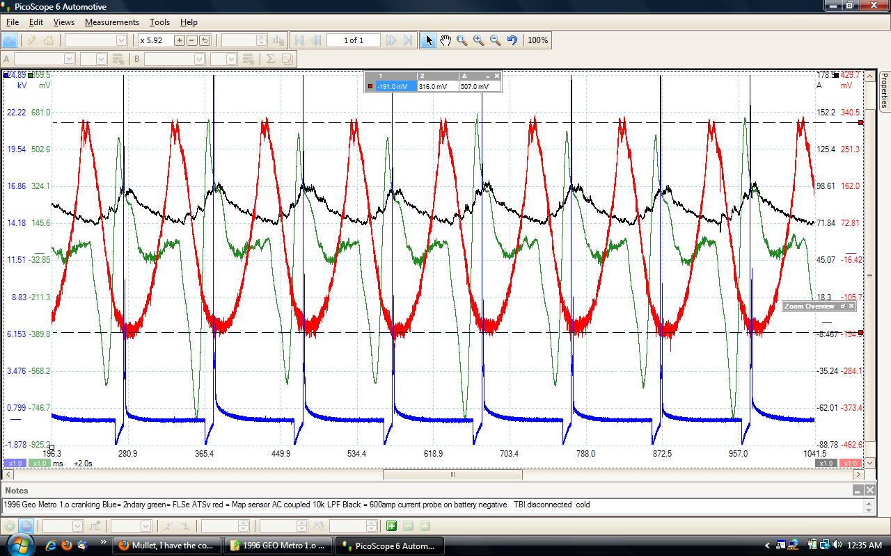
this simple waveform capture shows exhaust pressure per cylinder (green) with intake pressure (red) with secondary spark which roughly shows about 10 degrees before TDC of each cylinder
note
how UN even and erratic the green exhaust pressure / flow is
on a stock G10 Geo Metro with the engine not running , just operating the starter , that is because of the way the exhaust manifold is configured .
at higher rpm under load
exhaust flow is
tragic
but
it will be no WORSE than what the "alleged " header systems depicted will show
compare to this
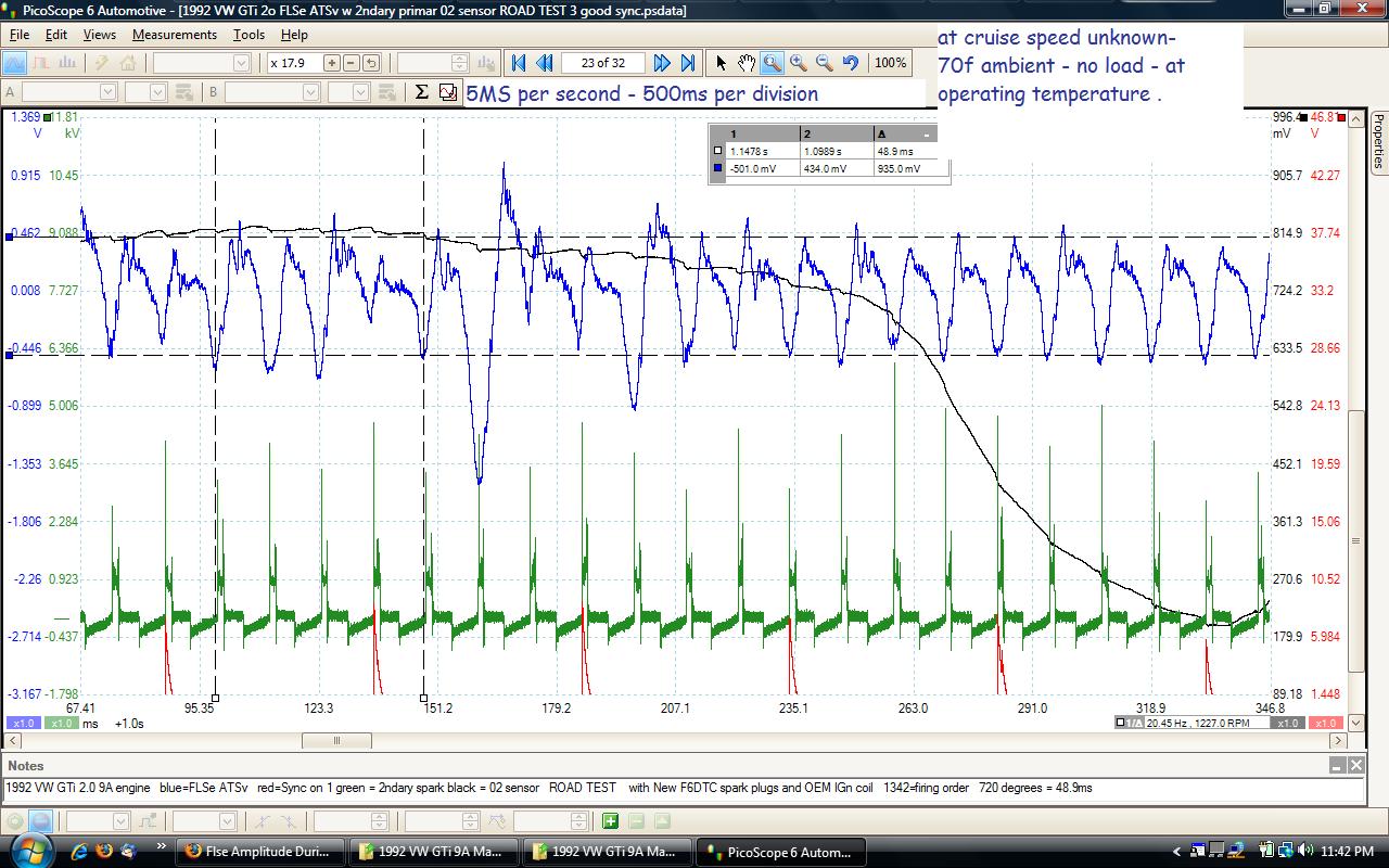
there is a long line misfire to the left of center but
excepting that
look at the blue trace , note how uniform each exhaust pulse is
at cruise around 40 to 45 mph
that is what is desired a uniform pulse train
you will never achieve a uniform pulse train with a knotted pretzel shaped exhaust
you will never see this using a dyno or hypothetical software
does this matter
yes it does
turbulence is never your friend when you are attempting to improve VE
and that is your goal to IMPROVE VE
you can not improve VE by reducing VE .
Last edited by mwebb; 11-22-2014 at 11:28 PM..
Reason: image was broken
|
|
|
|
|
11-22-2014, 11:55 PM
|
#49 (permalink)
|
|
EcoModding Apprentice
Join Date: Aug 2014
Location: Adelaide, Australia
Posts: 120
Thanks: 53
Thanked 54 Times in 33 Posts
|
Quote:
Originally Posted by mwebb
so
first off
i see some of the systems in images here in this thread are tightly woven
messes
flow in them is going to be UN consistent at best
and that is exactly what is NOT wanted
dynos are useless for measuring flow
imho
this simple waveform capture shows exhaust pressure per cylinder (green) with intake pressure (red) with secondary spark which roughly shows about 10 degrees before TDC of each cylinder
note
how UN even and erratic the green exhaust pressure / flow is
on a stock G10 Geo Metro with the engine not running , just operating the starter , that is because of the way the exhaust manifold is configured . |
I'm not sure exactly what you're getting at here? Obviously when you're just cranking the engine over, *nothing* is going to be operating within optimal design spec (except the starter motor and the ECU's startup mode routines). Nobody designs systems on a 1L 3 cylinder car engine to operate at their peak efficiency at 390rpm, that would just be nuts. Also, this is pretty much what the pressure in the exhaust port of a 4-stroke engine is *always* going to look like when you're cranking it over, regardless of whether it's got a manifold, a header, or the exhaust port is just open to the air (in which case the negative pressure spike when the valve closes will be a little smaller, but that's about it) - unless you have pipes 20 meters long, you won't get any resonance on that time scale, just the effects of the exhaust port opening and letting the air out...
As for bends and twists - sure, the onset of turbulence happens faster in a curved pipe than a straight one, but hot, recently burning gasses exploding out past a valve assembly are going to be turbulent from the get-go, and there ain't a thing you can do about that. For turbulent flow in a very light gas like air though, relatively gentle bends don't have a catastrophic effect on flow as you seem to be saying, obviously you want to avoid unnecessary bends (and unnecessarily tight bends in particular - if the flow detaches from the inner wall you're in real trouble) but the effects of a beneficial resonance will be dominant unless you've literally tied everything in a pretzel a couple of times over - a good header will be giving you a negative pressure pulse just before valve closing, below even atmospheric pressure.
And bendy bits don't stop you from getting a nice strong resonance happening, or this object would not exist
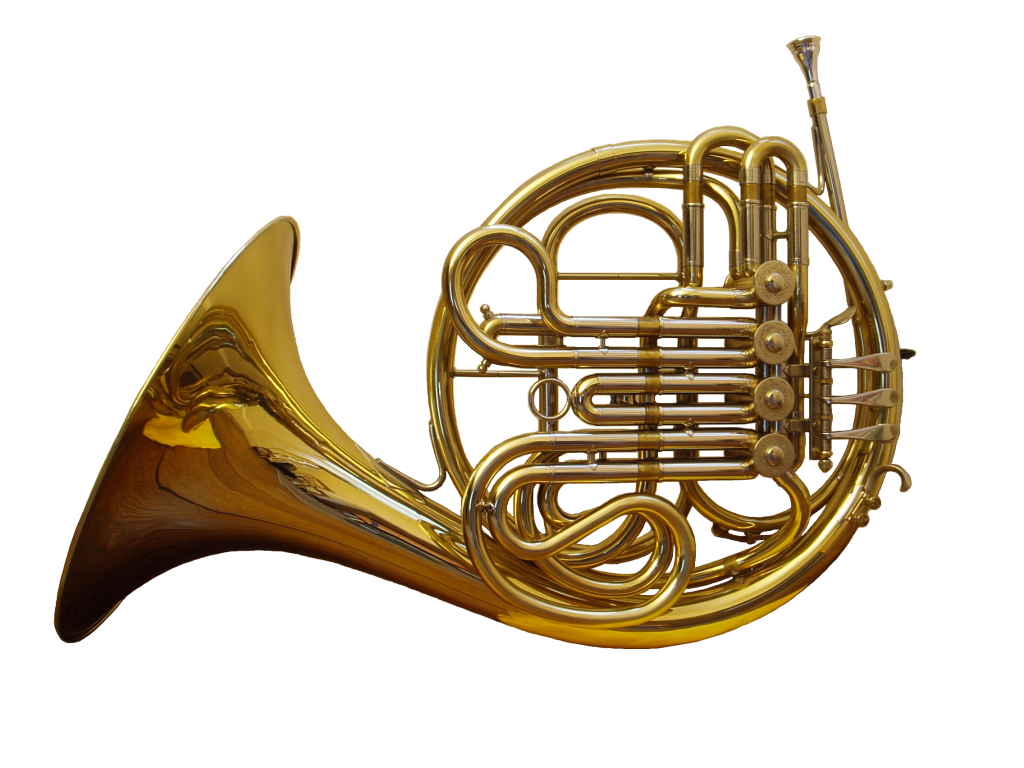
Last edited by Madact; 11-23-2014 at 12:07 AM..
Reason: Punctuation
|
|
|
|
|
11-23-2014, 04:31 AM
|
#50 (permalink)
|
|
EcoModding Lurker
Join Date: Nov 2014
Location: UK
Posts: 42
Thanks: 0
Thanked 12 Times in 12 Posts
|
Quote:
Originally Posted by Madact
but hot, recently burning gasses exploding out past a valve assembly are going to be turbulent from the get-go,
|
There are no explosions involved, the valves open smoothly on a smoothly curved cam, initially allowing a tiny flow which smoothly increases before being smoothly closed again. The exhaust gasses should flow smoothly out the ports and down the pipes. Even the burning of the fuel isn't an explosion as many people think, it starts burning at the spark and the flame spreads out smoothly through the piston giving a smooth increase in pressure.
If things start exploding then things are going wrong, that is what detonation is and that destroys engines.
The main job of the header is to transport the exhaust gasses, they will flow easier through nice straight pipes, putting extra curves in to get equal lengths seems very questionable to me.
|
|
|
|
|