 08-23-2014, 11:34 PM
|
#1001 (permalink)
|
|
Permanent Apprentice
Join Date: Jul 2010
Location: norcal oosae
Posts: 523
Thanks: 351
Thanked 318 Times in 215 Posts
|
I saw something on SBE's website (app notes) stating somewhat different numbers, depending on the application. For example, 3 phase, single phase, or pulse applications. I suppose your real quote from an engineer is the best we can hope for! 
The numbers I was calculating were sine waves, phase to neutral, and with my motor, it would be impossible to measure those values. (Actually, I'm not sure if the neutral is connected to ground)
Thanks again; this is a huge help!
- E*clipse
Quote:
Originally Posted by MPaulHolmes

The beauty of those ring capacitors is, "occasional spikes over 600v are not a good reason to get a higher voltage ring cap." That's a quote from one of the SBE engineers. They were trying to push the 450v cap on me when I was going to run it at 300v. They don't need much derating at all.
The 3 phases to neutral are 120Vac. But I think that only makes sense when talking about filtered real life sine waves that are 120 degrees apart. Starting with DC, we are just getting pwm'ed square waves that instantaneously don't look like 120Vac from phase to neutral. They have to be filtered before looking like that.
EDIT: Or maybe it really is 120Vac sine waves, 120 degrees out of phase that are across each phase coil, but the phase coil voltage (to neutral) is not accessible to us. Sure, let's go with that! haha.
|
|
|
|

|
 Today Today
|
|
|
|
 Other popular topics in this forum...
|
|
|
|
|
08-23-2014, 11:40 PM
|
#1002 (permalink)
|
|
Master EcoModder
Join Date: Sep 2010
Location: Saskatoon, canada
Posts: 1,488
Thanks: 746
Thanked 565 Times in 447 Posts
|
Quote:
Originally Posted by MPaulHolmes
I have no official motor in mind. I'm just lying in wait, ready to pounce like a puma, once I save up enough money.
|
Are you testing on your bench or in a vehicle? |
|
|
|
|
08-23-2014, 11:44 PM
|
#1003 (permalink)
|
|
PaulH
Join Date: Feb 2008
Location: Maricopa, AZ (sort of. Actually outside of town)
Posts: 3,832
Thanks: 1,362
Thanked 1,202 Times in 765 Posts
|
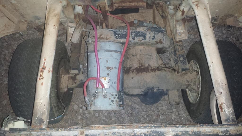
On a bench. I do have a golf cart with a DC motor inside, so a good choice for me would be a motor I could mate to the transmission. Like some sort of 3 phase AC golf cart motor, that's maybe 48 or 72vDC input that comes with an encoder. That would get the current up, and give the FOC more resolution.
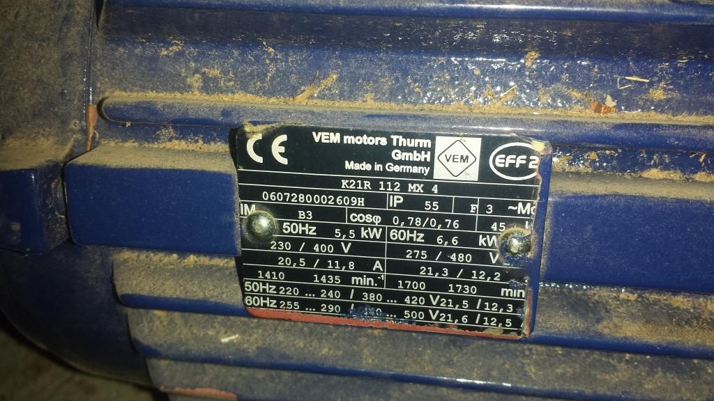
I have a 3 phase 12v BMW alternator that Otmar let me borrow. It doesn't have an encoder. I also have a 208vac 3/4HP I think. It even has an encoder, but I don't know if I can push enough current through it to actually test the FOC code. Sure I can get it to spin with a V/Hz sort of thing. Can you drive with V/Hz as the software? With an encoder, it could be pretty smart.
Last edited by MPaulHolmes; 08-24-2014 at 12:10 AM..
|
|
|
|
|
08-24-2014, 01:56 AM
|
#1004 (permalink)
|
|
Master EcoModder
Join Date: Sep 2010
Location: Saskatoon, canada
Posts: 1,488
Thanks: 746
Thanked 565 Times in 447 Posts
|
Quote:
Originally Posted by MPaulHolmes
On a bench. I do have a golf cart with a DC motor inside, so a good choice for me would be a motor I could mate to the transmission.
|
What model golf cart? I have not seen used golf carts with AC as yet. Perhaps a forklift? They have been running AC for a few years now. I think HPEVS started out with golf carts and fork trucks ...
Quote:
|
I have a 3 phase 12v BMW alternator that Otmar let me borrow. It doesn't have an encoder.
|
The alternator should take a fair bit of current. My car alternator outputs over 200 amps. What do the specs for the alternator list?
Bolting an encoder to whatever you are using as a load (like maybe a generator head?) may work OK. I have not tried this type of thing as yet.
Quote:
|
I also have a 208vac 3/4HP I think. It even has an encoder, but I don't know if I can push enough current through it to actually test the FOC code.
|
3/4 HP is maybe 3 amps full load current. If you stall the motor by coupling it to a load that is too large for it to move you could get between 6 and 8 times your full load current when you start up your controller, push a lot of current into the motor, and heat the motor up *REALLY* fast. I would advise 10 seconds or less and let the motor cool off for at least half an hour between tests.
Why do I know this? We overheat motors to failure at my day job a lot (I call them Light Emitting Motors - LEM), when the pumps that are being driven are mechanically jammed somehow. These pumps are just start/stop, no controller. The belt-driven ones just burn the belts off. The direct drive ones survive only if the overload blocks on their starters do their job. Sometimes they don't, or the wrong size overload was installed!
I would not be in the same room with the motor while testing if you decide to stall the motor.
Can you couple the alternator shaft to the 3/4 HP motor and use the encoder from the motor as feedback? The 3/4 HP motor (connected to a second controller) could be set to a lower speed and provide a load via regen?
Quote:
|
Sure I can get it to spin with a V/Hz sort of thing. Can you drive with V/Hz as the software? With an encoder, it could be pretty smart.
|
Yes, you can drive a motor (and a vehicle, for that matter) with V/Hz but it is not very efficient. The motor heats up. The FOC shifts the phase Voltage and Current (so I'm told) so that you are minimizing the core losses. With V/Hz you are doing a linear estimate on a non-linear load, and the extra current you pump into the motor is dumped as heat. We use V/Hz on pumps and fans. The load varies proportional to the cube of the speed. So 1/2 speed is about 1/8 load. Running in V/Hz is simple and allows us to replace motors without 'tuning' the controller to the new motor. But it wastes a bit of power.
I have no experience with an encoder on a V/Hz driven load. As I understand it, the controller does not have the option of changing the output voltage separate from the frequency when in V/Hz? |
|
|
|
|
The Following User Says Thank You to thingstodo For This Useful Post:
|
|
|
08-24-2014, 09:25 AM
|
#1005 (permalink)
|
|
PaulH
Join Date: Feb 2008
Location: Maricopa, AZ (sort of. Actually outside of town)
Posts: 3,832
Thanks: 1,362
Thanked 1,202 Times in 765 Posts
|
I thought this motor had been lost! It was hidden in a box buried in a corner of my shop.
I had just sort of given up on it. Like maybe it was left in my mother in laws garage (I know I left one motor up there), but I didn't see it the last time I was up there. I figured it had been thrown out.
Could I get 6-8 times the full load current for 10 seconds? I think I'll wrap the LEM 300 current sensor a few times to reduce the 300 down to maybe 100 (3 wraps). The reason I had gotten LEM 300's was because I wanted the hardware overcurrent to trip at 600amp (well suited to the IGBTs), and I was concerned about the hardware overcurrent tripping when the motors were in a stalled state. They make a LEM 50, but then the hardware overcurrent trip would be at 100amp. And I was thinking that if it's supposed to be more powerful than the 144v 500amp DC controller, then it better be at least 288vDC input, with 300amp per phase (since the IGBTs can handle that). Now I'm seeing all these AC motors that weigh 5 gazillion pounds, that are rated for like 20 amps. Are we stuck with AC motors whose peak power is much lower than 100kW if you want to actually fit it in a car?
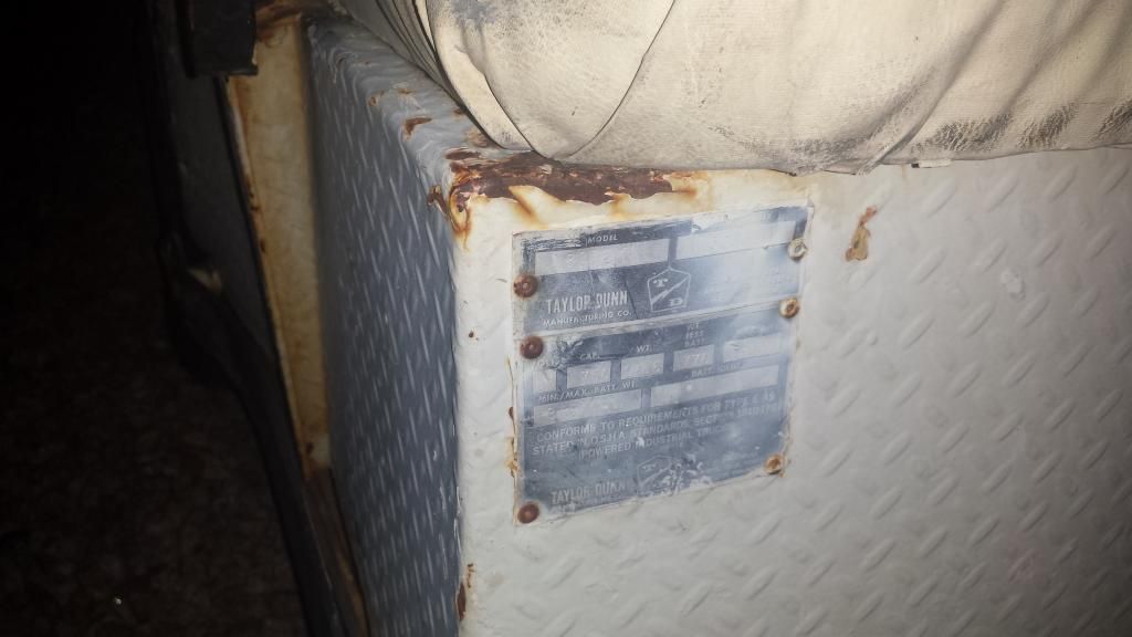
Here's the golf cart model:

 |
|
|
|
|
The Following User Says Thank You to MPaulHolmes For This Useful Post:
|
|
|
08-24-2014, 12:46 PM
|
#1006 (permalink)
|
|
Master EcoModder
Join Date: Sep 2010
Location: Saskatoon, canada
Posts: 1,488
Thanks: 746
Thanked 565 Times in 447 Posts
|
Quote:
Originally Posted by MPaulHolmes
Could I get 6-8 times the full load current for 10 seconds? I think I'll wrap the LEM 300 current sensor a few times to reduce the 300 down to maybe 100 (3 wraps).
|
Yes, you should be able to get 6X - 8X current on a stall. You can go longer than 10 seconds but at some point you risk damage to the insulation on the windings.
If you can fit 3 wraps of wire through the sensor - I'd try that.
Quote:
|
And I was thinking that if it's supposed to be more powerful than the 144v 500amp DC controller, then it better be at least 288vDC input, with 300amp per phase (since the IGBTs can handle that). Now I'm seeing all these AC motors that weigh 5 gazillion pounds, that are rated for like 20 amps. Are we stuck with AC motors whose peak power is much lower than 100kW if you want to actually fit it in a car?
|
The AC motors appear to increase the voltage and reduce the current. I use EVTV as examples, but there are many vendors. EVTV Motor Verks Store:
The Siemens motors that Azure Dynamics had made for them were 300V and 400A? With voltage sag on the pack about 100 kw. These are expensive for the DIYers, but appear to be well suited for vehicles.
Three phase electric motors for commercial or industrial use are rated for continuous duty. That appears to be why they are so large and heavy but have little horsepower. Their power limit is defined by how much heat they can get rid of in a 24/7 situation.
Since we, in an EV, only have enough battery for maybe an hour of driving and then the motor cools down all day while we are at work ... you can push the performance higher with lower weight. HPEVS has several motors that are physically quite small, but decent horswepower. HPEVS want to sell their motors as a package with the Curtis controller ... at least, that's how I see them advertised.
Another issue is the rotor design of an induction motor. We have some people in this group that have much more expertise in this area than I do. The summary is that induction motors have different 'sets' of rotor bars at different 'depths' from the surface of the rotor. Some are important for 'across the line' or 'direct online' starts. Others are more suited to controllers where there is not much slip. I have been hoping that someone would start to market rotors for the EV market .. to fit in T frame motors .. but I guess that's not a large market?
Heck, if the rotors were higher performance and lower weight, I might even buy them for my day job. We have about 20% of our motors on controllers, so we could use lighter and higher performance (lower slip) rotors. Then our mechanics and electricians would not complain as much about how heavy the motors are when they need to change them. |
|
|
|
|
08-24-2014, 12:57 PM
|
#1007 (permalink)
|
|
Master EcoModder
Join Date: Sep 2010
Location: Saskatoon, canada
Posts: 1,488
Thanks: 746
Thanked 565 Times in 447 Posts
|
Quote:
Originally Posted by e*clipse
The numbers I was calculating were sine waves, phase to neutral, and with my motor, it would be impossible to measure those values. (Actually, I'm not sure if the neutral is connected to ground)
|
Most (perhaps all) commercial and industrial induction motors have the frame as a ground point. A High Resistance Ground resistor is connected to the frame or ground on the power transormer, which goes to ground for the building, or ground grid. Measuring the voltage across the ground resistor detects a failure in one of your motors, where one phase has worn through the insulation and has put dangerous voltage on the frame of the motor.
I've been struggling with what to do on a vehicle. It's tough to isolate ALL of the metal on a motor from the car frame. But if you are getting into 300 or 600VDC for a pack, just leaning on the car and touching the motor (or controller, or whatever the worn-through wire is touching) is going to give you a NASTY poke, perhaps a 'you're dead' shock.
There are BMS's that claim to monitor this. I have no experience with them. They'd have to convince me that they know what they are doing. |
|
|
|
|
The Following User Says Thank You to thingstodo For This Useful Post:
|
|
|
08-24-2014, 02:25 PM
|
#1008 (permalink)
|
|
Permanent Apprentice
Join Date: Jul 2010
Location: norcal oosae
Posts: 523
Thanks: 351
Thanked 318 Times in 215 Posts
|
That's the thing that's bugging me... Even though I have the motor in many pieces, there isn't an obvious neutral connection. As far as I know (from looking at analyses of similar motor by the DOE, the motor is wired wye, not delta. I just can't find the magic center point. 
Acually, I'll test to see if there is any conductivity between any phase and the case. That would be interesting.
I did have an electric car conversion book that was very specific that the battery, controller, and motor needed to be isolated from the chassis. You shouldn't use the chassis as "ground."
- Just the experience of building my solar system...
- E*clipse
Quote:
Originally Posted by thingstodo
Most (perhaps all) commercial and industrial induction motors have the frame as a ground point. A High Resistance Ground resistor is connected to the frame or ground on the power transormer, which goes to ground for the building, or ground grid. Measuring the voltage across the ground resistor detects a failure in one of your motors, where one phase has worn through the insulation and has put dangerous voltage on the frame of the motor.
I've been struggling with what to do on a vehicle. It's tough to isolate ALL of the metal on a motor from the car frame. But if you are getting into 300 or 600VDC for a pack, just leaning on the car and touching the motor (or controller, or whatever the worn-through wire is touching) is going to give you a NASTY poke, perhaps a 'you're dead' shock.
There are BMS's that claim to monitor this. I have no experience with them. They'd have to convince me that they know what they are doing.
|
|
|
|
|
|
The Following User Says Thank You to e*clipse For This Useful Post:
|
|
|
08-24-2014, 03:03 PM
|
#1009 (permalink)
|
|
Master EcoModder
Join Date: Sep 2010
Location: Saskatoon, canada
Posts: 1,488
Thanks: 746
Thanked 565 Times in 447 Posts
|
Quote:
Originally Posted by e*clipse
That's the thing that's bugging me... Even though I have the motor in many pieces, there isn't an obvious neutral connection. As far as I know (from looking at analyses of similar motor by the DOE, the motor is wired wye, not delta. I just can't find the magic center point.
Acually, I'll test to see if there is any conductivity between any phase and the case. That would be interesting. |
Are you just interested in where the neutral point is?
As I understand it, you can find the 'neutral point' if you dig through the windings and find where the star point is. It's just a connection between the coils, and it is insulated after it is braised or bonded or whatever method they use to connect them. It should be on one of the ends, and there will be at least one longer insulated wire (from the coil that does not end up near there) coming to it.
That's different from the 'ground point'. The ground is there to help keep you safe if there is a failure in the motor. If Phase A wears through the insulation, and the frame is now at the same voltage as A phase .. there should be a fuse blow or a breaker trip because the ground is connected back to the source of the power - battery pack, transformer, etc.
If you have a .. I think it's a 12 lead motor .. you can wire it for 460V or 230V, Y or delta. Both ends of each coil, 6 coils total, 2 for each phase, are brought out to the motor junction box. Then finding the neutral is easy. The junction box is confusing just because there are so many terminals to deal with.
If you get a resistance reading between the frame and any of your three phases of less than about 1 mega ohm then there is a problem. The insulation on the motor should measure 10X or 100X that.
Y or Star connected has a bit higher voltage and a bit lower current. Delta has higher current but lower voltage. I think Delta has better torque .. but don't quote me. We have a couple of compressors that start up under load and have the first stage as delta and the second stage as Y. It matters to motor rewinders, and it matters when you are ordering a motor so you get what you need at the right voltage. The rest of the time no one seems to care. |
|
|
|
|
08-24-2014, 03:05 PM
|
#1010 (permalink)
|
|
Master EcoModder
Join Date: Sep 2010
Location: Saskatoon, canada
Posts: 1,488
Thanks: 746
Thanked 565 Times in 447 Posts
|
Quote:
Originally Posted by e*clipse
I did have an electric car conversion book that was very specific that the battery, controller, and motor needed to be isolated from the chassis. You shouldn't use the chassis as "ground."
|
Did the book give you any guidance on HOW to isolate the motor, controller and battery pack from ground, or how to detect when that isolation was broken?
|
|
|
|
|


