Go Back   EcoModder Forum > EcoModding > Fossil Fuel Free
Register Now
 Register Now
 

Reply  Post New Thread
 
Submit Tools LinkBack Thread Tools
Old 12-08-2014, 02:14 PM   #1391 (permalink)
Permanent Apprentice
 
Join Date: Jul 2010
Location: norcal oosae
Posts: 523
Thanks: 351
Thanked 314 Times in 215 Posts
A couple of quick thoughts regarding this different switching method:

PICs have an independant switching mode - I messed with it a bit for Switched Reluctance motors.

Does this method require acces to the center of the wye?

- E*clipse

  Reply With Quote
Alt Today
Popular topics

Other popular topics in this forum...

   
Old 12-08-2014, 02:33 PM   #1392 (permalink)
EcoModding Apprentice
 
Join Date: Nov 2012
Location: East Midlands
Posts: 180
Thanks: 13
Thanked 81 Times in 52 Posts
Quote:
Originally Posted by e*clipse View Post
A couple of quick thoughts regarding this different switching method:

PICs have an independant switching mode - I messed with it a bit for Switched Reluctance motors.

Does this method require acces to the center of the wye?

- E*clipse
No, that would be a bit discriminating for those guys running delta
  Reply With Quote
The Following User Says Thank You to cts_casemod For This Useful Post:
e*clipse (12-08-2014)
Old 12-08-2014, 03:47 PM   #1393 (permalink)
EcoModding Apprentice
 
Join Date: Nov 2012
Location: East Midlands
Posts: 180
Thanks: 13
Thanked 81 Times in 52 Posts
Finished the single phase simulation, using square wave, now lets make it 3 phase.
Attached Thumbnails
Click image for larger version

Name:	Untitled.gif
Views:	84
Size:	46.3 KB
ID:	16576  
  Reply With Quote
Old 12-08-2014, 04:18 PM   #1394 (permalink)
Permanent Apprentice
 
Join Date: Jul 2010
Location: norcal oosae
Posts: 523
Thanks: 351
Thanked 314 Times in 215 Posts
Ok, I'm still trying to wrap my head around this; here are some relivant papers on the subject.

The first one is a thesis, which actually describes it quite well on pages 37-40.
http://eprints.usm.my/9031/1/DESIGN_...POLAR_SPWM.pdf

This is an excerpt from a book from the guy who came up with the concept (I think)

The Industrial Electronics Handbook - J. David Irwin - Google Books

It seems like it should be possible to implement a 3-phase FOC control with this topology, even though most papers I can find only talk about single phase. It also seems to be implemented with comparators and triangular reference frequencies(at least in explanation) The PIC basically uses an interrupt and counter to produce the triangle. I guess this would really require a modification to the SVM that's done near the end of the control loop.

One thing that seems very interesting is the diodes are used as active switching devices critical for the operation, not just current dump paths for the inductor. The result is an effective switching frequency that is double of the base frequency. That's ok with me, I was planning to run mine at a higher base frequency anyway.

-E*clipse


Quote:
Originally Posted by cts_casemod View Post
No, that would be a bit discriminating for those guys running delta
  Reply With Quote
Old 12-08-2014, 04:23 PM   #1395 (permalink)
Permanent Apprentice
 
Join Date: Jul 2010
Location: norcal oosae
Posts: 523
Thanks: 351
Thanked 314 Times in 215 Posts
Were you able to get an output RMS voltage close to the input DC?

- E*clipse

Quote:
Originally Posted by cts_casemod View Post
Finished the single phase simulation, using square wave, now lets make it 3 phase.
  Reply With Quote
Old 12-08-2014, 04:24 PM   #1396 (permalink)
EcoModding Apprentice
 
Join Date: Nov 2012
Location: East Midlands
Posts: 180
Thanks: 13
Thanked 81 Times in 52 Posts
Quote:
Originally Posted by e*clipse View Post
Ok, I'm still trying to wrap my head around this; here are some relivant papers on the subject.

The first one is a thesis, which actually describes it quite well on pages 37-40.
http://eprints.usm.my/9031/1/DESIGN_...POLAR_SPWM.pdf

This is an excerpt from a book from the guy who came up with the concept (I think)

The Industrial Electronics Handbook - J. David Irwin - Google Books

It seems like it should be possible to implement a 3-phase FOC control with this topology, even though most papers I can find only talk about single phase. It also seems to be implemented with comparators and triangular reference frequencies(at least in explanation) The PIC basically uses an interrupt and counter to produce the triangle. I guess this would really require a modification to the SVM that's done near the end of the control loop.

One thing that seems very interesting is the diodes are used as active switching devices critical for the operation, not just current dump paths for the inductor. The result is an effective switching frequency that is double of the base frequency. That's ok with me, I was planning to run mine at a higher base frequency anyway.

-E*clipse
The frequency doubling is not really related to the method itself.
It just occurs because since each PWM only takes care of half of the sine wave, rather than the full sine have as it happens with bipolar schemes (center aligned PWM). That also results in twice the resolution or half the ripple, with a resulting decrease in the THD.

Check this paper for a 3 phase implementation and explanation

AN4429 or here Freescale

Last edited by cts_casemod; 12-08-2014 at 05:00 PM..
  Reply With Quote
The Following User Says Thank You to cts_casemod For This Useful Post:
e*clipse (12-08-2014)
Old 12-08-2014, 04:29 PM   #1397 (permalink)
EcoModding Apprentice
 
Join Date: Nov 2012
Location: East Midlands
Posts: 180
Thanks: 13
Thanked 81 Times in 52 Posts
Quote:
Originally Posted by e*clipse View Post
Were you able to get an output RMS voltage close to the input DC?

- E*clipse
yes, I used a square wave, so my output voltage swings from +DCLINK to - DC LINK.

On the example above, the input was 10V, and the line to line voltage is 20V.

BTW, this is nothing new, thats how cheap square wave inverters (12 to 110 or 230V) work. A switch mode power supply boosts the 12V to 320 (the image is wrong, Vpeak is 340V!!) and then a mosfet bridge just inverts the polarity of the output with a dead time in between (quasi sinusoidal output). I just never remembered I could use the same technique on a motor inverter until this morning

  Reply With Quote
Old 12-08-2014, 06:58 PM   #1398 (permalink)
Master EcoModder
 
P-hack's Avatar
 
Join Date: Oct 2012
Location: USA
Posts: 1,408

awesomer - '04 Toyota prius
Thanks: 102
Thanked 252 Times in 204 Posts
phase reversing only works with single phase. The most you can get with 3 phase is with svpwm (which reverses the phases as much as it can) AFAIK

i.e. a 300 volt battery with svpwm can create a 300x1.73 v peak to peak 3 phase.
aka 259 peak, which is 180vrms per phase. (not phase to phase), maybe 317v phase 2 phase rms (edit WRONG).

I ran some simulations using a 6 lead motor with each phase on a full bridge so each could be reversed completely, and it didn't help one bit compared to svpwm switching for a given battery voltage. SVPWM can also save on switching losses if you hold the lowest phase to ground (or the highest to the rail) and scale the other phases accordingly.
http://ethesis.nitrkl.ac.in/1133/1/C..._using_PWM.pdf figure 21.

maybe I made an error somewhere, but I'm pretty sure about this.

Edit: I lied, a 300v battery, using SVPWM can create 213v (line 2 line rms) 3 phase. It is the same for single phase (213v rms from 300v peak, aka 600v peak/peak with full bridge).

Last edited by P-hack; 12-08-2014 at 07:35 PM..
  Reply With Quote
The Following User Says Thank You to P-hack For This Useful Post:
mpgmike (02-06-2022)
Old 12-08-2014, 07:42 PM   #1399 (permalink)
EcoModding Apprentice
 
Join Date: Nov 2012
Location: East Midlands
Posts: 180
Thanks: 13
Thanked 81 Times in 52 Posts
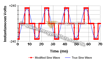
I finished the simulations.

I used a modified sine wave, but the same applies for a square waveform.

Bipolar PWM:


------------------------------------------------------

Unipolar PWM


According to one of my books, the first simulation was based on:

The first case, where peak voltage is line to line I followed the diagram on this page:


With the Following firing order


For the second case, where line to line voltage = 2*DC_LINK, I replaced T2, T4 and T6 states with the inverted states of T1, T3 and T5 as sugested on the previous links I posted on #1396.

I guess now its a matter of trying this with SPWM with complementary mode PWM rather than center aligned PWM (These are the definitions Atmel uses, microchip may use something different)
  Reply With Quote
Old 12-08-2014, 08:03 PM   #1400 (permalink)
Master EcoModder
 
P-hack's Avatar
 
Join Date: Oct 2012
Location: USA
Posts: 1,408

awesomer - '04 Toyota prius
Thanks: 102
Thanked 252 Times in 204 Posts
for me the "aha" moment was when I used a 3 phase source with a 3 phase rectifier (like doing a maze in reverse). I selected 3 sine sources that had ~213v phase2phase here (individually 176v peak). As you can see, the "bus" voltage is 300 volts, representing a 300v battery, and the phase to ground voltages (red blue cyan) are what needs to come out of the igbts (and is one of the svpwm waveforms, NOT spwm). And most importantly, the phase to phase voltage (purple) is 600 volts peak to peak (and ltspice is awesome )

So the phases are pretty much fully reversed with the SVPWM pattern.

Unfortunately that 300v peak purple line 2 line is still ~213vrms (i.e. 208v industrial motor at rated voltage).


Attached Thumbnails
Click image for larger version

Name:	svpwm.png
Views:	582
Size:	56.8 KB
ID:	16578  

Last edited by P-hack; 12-08-2014 at 08:21 PM..
  Reply With Quote
The Following User Says Thank You to P-hack For This Useful Post:
mpgmike (02-06-2022)
Reply  Post New Thread


Thread Tools


Similar Threads
Thread Thread Starter Forum Replies Last Post
Paul & Sabrina's cheap DIY 144v motor controller MPaulHolmes Open ReVolt: open source DC motor controller 7381 08-02-2023 10:55 PM
Paul & Sabrina's Cheap EV Conversion MPaulHolmes Fossil Fuel Free 542 11-12-2016 09:09 PM
Contest! Name Paul & Sabrina's controller MetroMPG Forum News & Feedback 120 10-22-2011 01:59 PM


Powered by vBulletin® Version 3.8.11
Copyright ©2000 - 2024, vBulletin Solutions Inc.
Content Relevant URLs by vBSEO 3.5.2
All content copyright EcoModder.com