 09-29-2015, 05:48 PM
|
#2111 (permalink)
|
|
Permanent Apprentice
Join Date: Jul 2010
Location: norcal oosae
Posts: 523
Thanks: 351
Thanked 318 Times in 215 Posts
|
Quote:
Originally Posted by danibjor

I totally agree on the open source part. I'm all pro OS and have both used and contributed on OS projects.
Anyhow, TI have a video where they talk about the implementation, and for me whos new to flux, back emf and such - by watching this, i got a good understanding in how they think and how their algorithms work, without knowing about the code.
Could be I'm way of, but they got some clever thinking going on there.. |
Oh! This video is by Dave Wilson.  He's a very good teacher, and his app notes and videos helped (and continue to help  ) my understanding considerably. Check out this video about Field Oriented Control:
If it helps, you may also want to check out some app notes he has over there @ TI. 
Take care,
E*clipse
|
|
|

|
|
The Following User Says Thank You to e*clipse For This Useful Post:
|
|
 Today Today
|
|
|
|
 Other popular topics in this forum...
|
|
|
|
 09-29-2015, 06:00 PM
|
#2112 (permalink)
|
|
Permanent Apprentice
Join Date: Jul 2010
Location: norcal oosae
Posts: 523
Thanks: 351
Thanked 318 Times in 215 Posts
|
Ok, on my silly little problem... ( Motor Control? I can't get the debugger to talk..)
There is a pullup resistor from MCLR to Vdd. (yes, it should be there)
I measured the Vdrop across it, and it's 2.083V, when plugged into the ICD2. If not plugged in, there's no Vdrop.
The resistor measures 4.53KOhms. That's solidly in the 1K > 10K range Microchip specs.
All the other connections on the circuit board are just what they should be. 
It seems strange that it pulls down to 2.86V when the debugger is not doing anything. The ICD manual shows a brief internal circuit around the connection stuff, and there is no pull-down resistor mentioned. The connection to MCLR is internally +5V or GND.  |
|
|

|
|
The Following User Says Thank You to e*clipse For This Useful Post:
|
|
 09-29-2015, 06:16 PM
|
#2113 (permalink)
|
|
Master EcoModder
Join Date: Sep 2010
Location: Saskatoon, canada
Posts: 1,488
Thanks: 746
Thanked 565 Times in 447 Posts
|
Quote:
Originally Posted by MPaulHolmes

The sensorless is working, but now I'm fine tuning it so it works as good as possible. Also it was getting really oscillatory after a certain RPM
|
I am open to a new hex file, even to confirm the oscillations.
It would be cool to lower the max-rpm and have the controller shut down when I hit, say 4000 rpm  |
|
|

|
|
The Following User Says Thank You to thingstodo For This Useful Post:
|
|
 09-29-2015, 06:31 PM
|
#2114 (permalink)
|
|
Master EcoModder
Join Date: Sep 2010
Location: Saskatoon, canada
Posts: 1,488
Thanks: 746
Thanked 565 Times in 447 Posts
|
Quote:
Originally Posted by e*clipse

Ok, on my silly little problem... ( Motor Control? I can't get the debugger to talk..)
There is a pullup resistor from MCLR to Vdd. (yes, it should be there)
I measured the Vdrop across it, and it's 2.083V, when plugged into the ICD2. If not plugged in, there's no Vdrop.
The resistor measures 4.53KOhms. That's solidly in the 1K > 10K range Microchip specs.
|
The ICD2 may be trying to perform a reset and it's not quite making it there? If the ICD2 can only sink 0.63 milliamps (2.86V / 4.53K) .. that seems unreasonably low. It should be able to sink at least 10 mA which would be *MORE* than adequate.
The ICD2 is a bit older .. what if it presents a load to the MCLR which is higher (at 0.63 mA) than the controller expects? Is it reasonable to put a 1K6 in parallel with the 4K5? (works out to 1K2 by my math). The voltage on MCLR should rise to around 4.25V ...
... but then again ... it's not MY hardware we're talking about modding  |
|
|

|
|
The Following User Says Thank You to thingstodo For This Useful Post:
|
|
 09-29-2015, 07:58 PM
|
#2115 (permalink)
|
|
Permanent Apprentice
Join Date: Jul 2010
Location: norcal oosae
Posts: 523
Thanks: 351
Thanked 318 Times in 215 Posts
|
I saw a couple things that might help.
1) Paul - If you look @ section 8.3.1 in the FRM, they actually recommend a capacitor from MCLR to ground!  I guess its for the Power On Reset function, but it directly contradicts their debugger hardware. I'd say that was their mistake, not yours. 
2) Regarding the voltages, It seems there may be a decent possibility that if I plugged it in backwards, I would get the values I'm seeing.
Pin 1 (MCLR) on the target board has a 4.53K pullup to 4.96V
If it's connected to PGC by reversing the plug, there's a 4.7K pulldown to gnd, according to a ICD2 diagram. This would result in a 0.53737mA current and a voltage of 2.52V from MCLR to GND. If their internal resistor were a bit higher, like 6.25K, the numbers could match.
Pin 2 (Vdd) onthe target board is simply 4.96V.
If it's connected to PGD by reversing the plug, there's a 4.7K pulldown to gnd. Since there's no pullup resistor, the voltage would read 4.96V.
Pin3 (GND) would not change, as a reversed connector would pivot around here.
Pin4 (PGD) would read 5V??
Pin5 (PGC) would also read 5V??
Maybe I need some info about the PGD and PGC pins.. |
|
|

|
 09-29-2015, 09:39 PM
|
#2116 (permalink)
|
|
Permanent Apprentice
Join Date: Jul 2010
Location: norcal oosae
Posts: 523
Thanks: 351
Thanked 318 Times in 215 Posts
|
Screwt! 
Oh well; just bought a new PICKIT3. Something really bugs me about buying a new $50 thing to replace a $200 thing, when the only thing wrong is software. (config files, drivers, etc). After reading a big long thread about these problems (which weren't fixed, apparently with the ICD3) it seems not worth the time to fix it. 
I'm going out to the shop to pound on some metal.
- E*clipse |
|
|

|
|
The Following User Says Thank You to e*clipse For This Useful Post:
|
|
 09-29-2015, 11:21 PM
|
#2117 (permalink)
|
|
Master EcoModder
Join Date: Sep 2010
Location: Saskatoon, canada
Posts: 1,488
Thanks: 746
Thanked 565 Times in 447 Posts
|
Quote:
Originally Posted by thingstodo

I get a warning when I program with the PICkit 3 - the hex file loads with no errors, but when I verify there is a mismatch at some address. I'll check when I get home.
|
I guess logging the error is a bit moot at the moment ..
.. plus I forgot and it's getting late. |
|
|

|
|
The Following User Says Thank You to thingstodo For This Useful Post:
|
|
 09-30-2015, 12:12 AM
|
#2118 (permalink)
|
|
Permanent Apprentice
Join Date: Jul 2010
Location: norcal oosae
Posts: 523
Thanks: 351
Thanked 318 Times in 215 Posts
|
Quote:
Originally Posted by thingstodo

I guess logging the error is a bit moot at the moment ..
.. plus I forgot and it's getting late.
|
No worries!  Thanks for remembering.
It may help in the future to figure out that error. My problem is it wouldn't load at all; even a "blinky light" test. 
To be honest, that ICD2 has been a pain anyway; it's a royal pain to simply get the USB driver to work - I'm not kidding. If you're blessed and lucky it might work; then you tippy toe around so you don't upset the debugger gods.  .
So, I'm happy to religate it to the parts drawer and be on the same page w/ you guys.  |
|
|

|
|
The Following User Says Thank You to e*clipse For This Useful Post:
|
|
 09-30-2015, 12:21 AM
|
#2119 (permalink)
|
|
Master EcoModder
Join Date: Sep 2010
Location: Saskatoon, canada
Posts: 1,488
Thanks: 746
Thanked 565 Times in 447 Posts
|
Quote:
Originally Posted by e*clipse

To be honest, that ICD2 has been a pain anyway; it's a royal pain to simply get the USB driver to work - I'm not kidding. If you're blessed and lucky it might work; then you tippy toe around so you don't upset the debugger gods.  .
So, I'm happy to religate it to the parts drawer and be on the same page w/ you guys.  |
I have an older programmer as well, and gave up on it since I didn't remember how to use it, and it did not support the dsPIC series (too old) ...
Your sanity is worth the $50! |
|
|

|
|
The Following User Says Thank You to thingstodo For This Useful Post:
|
|
 09-30-2015, 04:45 PM
|
#2120 (permalink)
|
|
PaulH
Join Date: Feb 2008
Location: Maricopa, AZ (sort of. Actually outside of town)
Posts: 3,832
Thanks: 1,362
Thanked 1,202 Times in 765 Posts
|
Here are a couple graphs:
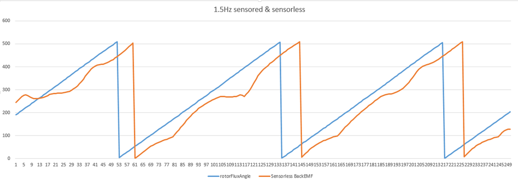
back emf angle (found sensorlessly vs the rotor flux angle found using the encoder and a bunch of random formulas haha):
Here is a graph of the sensorless BACK EMF angle lagging behind the sensored rotor flux angle at about 1.5Hz mechanical:

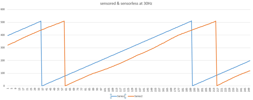
Here's a graph of the motor post spinning at 30.1Hz (x-axis ticks are 0.0001 sec):

Notice how nicely the back emf angle is tracking the rotor flux angle!! Even at 1.5Hz it's really not doing that horribly. I think I can improve on the 1.5Hz thing too and push it below 1Hz.
I'll get a hex file to you, and you can try out the sensorless code. although, I haven't actually used the sensorless to drive the motor yet. I was just trying to verify that I could obtain the rotor flux angle from the back emf angle somehow. It looks like you just subtract off like 20% of a period, but I think I remember someone saying that it's actually 90 degrees offset, so maybe my sensored rotor flux angle is off by a few %?
Hey! We could have a contest to see which spins the motor post faster. The one that spins it the fastest is making better use of the fixed Id and Iq!
First, we need to determine your motor's stator and rotor inductance, and a stator coil resistance. In my case, it works fine to just use the same rotor inductance as stator inductance. To figure out the stator inductance, we have to run a test and measure the offset of 2 waveforms. I'll set it up, and make sure it's working on my end before sending it over to you so you don't get stuck with a crappy hex file.
Last edited by MPaulHolmes; 09-30-2015 at 05:44 PM..
|
|
|

|
|
The Following 4 Users Say Thank You to MPaulHolmes For This Useful Post:
|
|
|