07-07-2010, 05:58 PM
|
#161 (permalink)
|
|
Left Lane Ecodriver
Join Date: Aug 2008
Location: Buffalo, NY, USA
Posts: 2,257
Thanks: 79
Thanked 287 Times in 200 Posts
|
I replaced the voltage regulator, but the board still doesn't work. I have some things hooked up right, I know. I can use the joystick to dial in one bar of regen, but that's not the most useful thing in the world. I may have hooked something up wrong, or more likely melted one of the IC's with my iron. It's tough when you're creating a board layout ad hoc from a schematic.
Oh, well. $17 worth of components in the trash, and I've ordered MIMA C - the full featured version which adds battery temperature probes, fan control, a method of reading the battery current sensor instead of Honda's lying gauge, and the option to program your own MAP sensor based assist/regen scheme. Maybe it is the feature creep that priced MIMA C beyond the reach of most enthusiasts. I've opted for the ~$200 assemble-it-yourself version, but I really wish there were a $50 pre-built MIMA L.
Boat tail: I will not meet my project goals without one. I've placed an order with a metals supplier, and it was supposed to be in on Monday but it's not here yet. I will complete a temporary aluminium and coroplast boat tail Soon(tm).
|
|
|

|
 Today Today
|
|
|
|
 Other popular topics in this forum...
|
|
|
|
|
07-09-2010, 12:03 AM
|
#162 (permalink)
|
|
Left Lane Ecodriver
Join Date: Aug 2008
Location: Buffalo, NY, USA
Posts: 2,257
Thanks: 79
Thanked 287 Times in 200 Posts
|
It's come to my attention that I never wrote about my kill switch. Here's a how-to.
Having a manual kill switch moved me from around 45mpg on very short trips to around 60mpg. It's a boon around town, though not as useful on the highway. It eliminates engine-on time sitting at red lights when the cabin heater is on, or when the car's not fully warmed up, or when you've got a good neutral coast going.
Installing a kill switch on the Insight is harder than on most cars, but I still recommend it. You need to kill all three fuel injectors, and then you need the clutch switch held closed so the engine doesn't auto-restart. You could take care of the clutch switch with a circuit board, or use your left leg until you're below 20mph, but I'm using an assist/regen disable switch (see also here).
Killing the fuel injectors is easy: pass each of the injector signals through a relay. The relay I used opens three different circuits simultaneously when you turn it on. I cut in to the injector wires at the ECU, which is located in the passenger footwell below the carpet. On one side of my cut, I attached a spade connector. On the other side, I soldered on a 6" length of wire with a spade connector on the end. Then plug the injector wires in to the relay.


IGP1 and IGP2 have +12V, INJ1-3 are the injectors, and if you want a ground, I think that's what PG1 and PG2 are.
One leg of the relay's coil is attached to a +12V rail at the ECU, and the other leg goes to a momentary switch zip-tied to the gear knob. The other leg of said momentary switch goes to ground. Press the button, and it powers up the relay and kills the engine.

You can hit the switch to kill the engine at any time. The engine will go in to auto-stop and stay there until you put it into gear, open the clutch switch, or tap the throttle. This makes EOC a breeze in the Insight. Plus, you retain power steering, airbags, mpg instruments, and everything else while coasting.
Limitations: unless you build the proper FAS circuitboard or a DC/DC converter toggle switch, your charging system shuts down during an engine kill. Also, due to the interaction of my brake lights and my IMA disable switch, if you lift off of the brakes above 20mph, the engine re-starts and has to be killed again if desired.
Last edited by RobertSmalls; 07-09-2010 at 12:08 AM..
|
|
|
|
|
07-13-2010, 10:03 PM
|
#163 (permalink)
|
|
Left Lane Ecodriver
Join Date: Aug 2008
Location: Buffalo, NY, USA
Posts: 2,257
Thanks: 79
Thanked 287 Times in 200 Posts
|
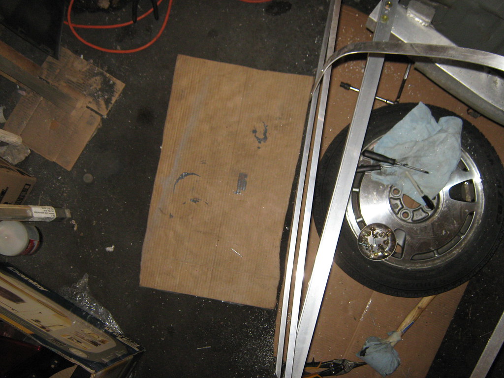
I've framed out a "temporary" boat tail in aluminium. It's a major scaling back of ambition, but I think that's appropriate given the diminishing marginal returns on adding length to the tail. Also, I've broken up with a girl who was very tolerant of my modding (actually, she didn't notice most of the mods  ), which has really led me to try to keep the car looking normal. Although I can handle a "funny looking car" like a stock Insight, I'm not in a position at the moment to drive around a "crazy looking car", from which you'd expect an excitedly shouting man in a lab coat to jump out with Erlenmeyer flasks in both hands (for this is how I presume engineers and scientists are perceived by the public). That combined with the fact I drive so few miles, mean this boat tail is coming off after the weekend. 100mpg? Fun, but I don't need it.
But enough about me. Here's some pics of what I've got:
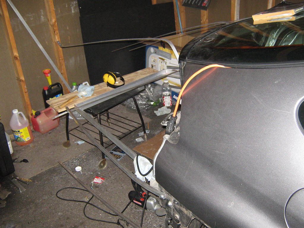
Here it is starting to take shape. Before I got to this point, I spent quite a bit of time looking at it thinking about what to do next.
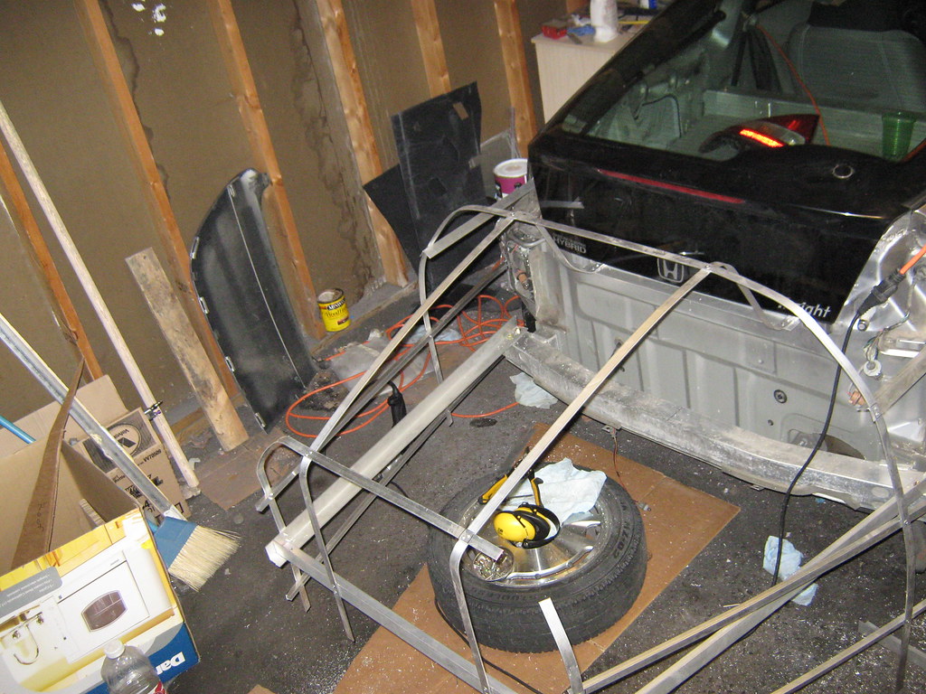
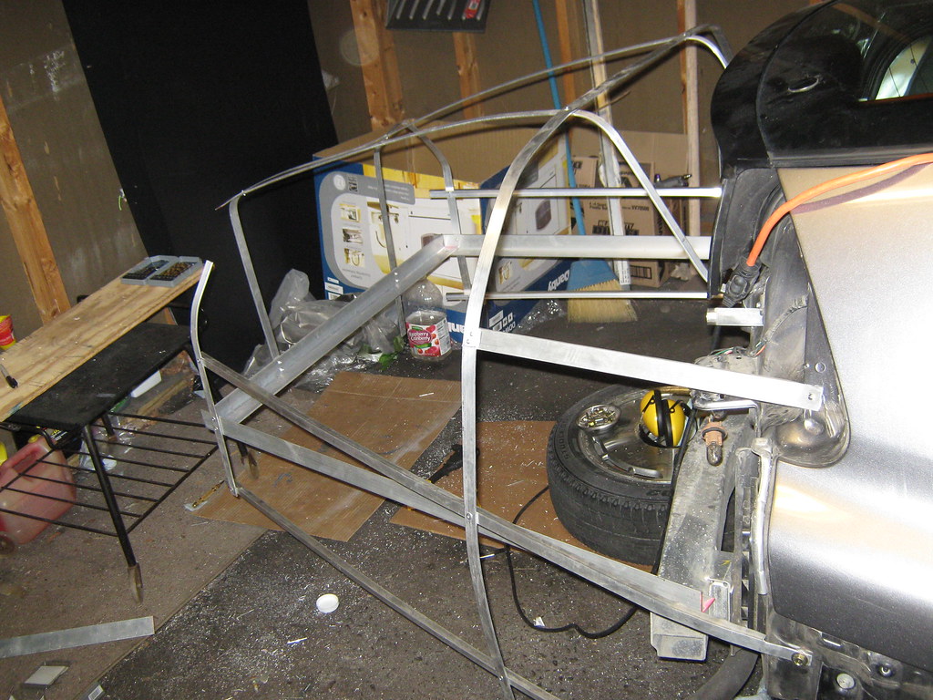
Two "overview" pictures.
A tire is sitting one one of my templates for the curvature of the side, holding it in place. Establishing a frame of reference and a centerline was more time consuming than you'd think. This photo shows that the frame matches the curvature of the template, slightly better than it looks in the photo.
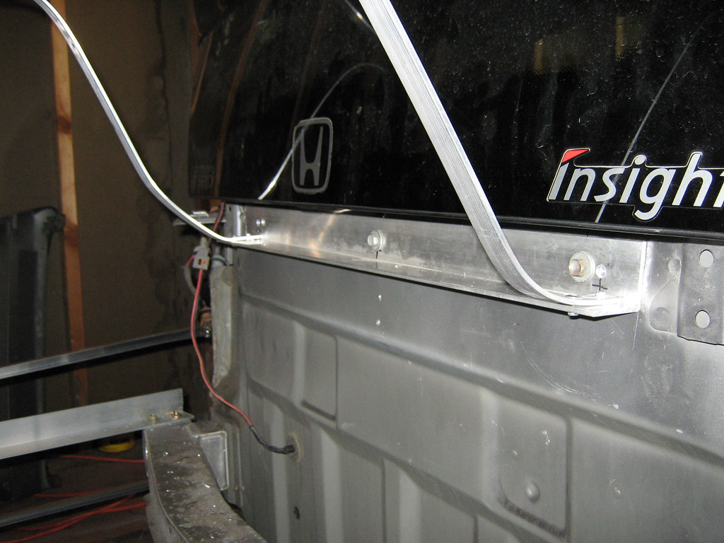
The upper attachment point. I unbolted the stock bumper cover holder, and used these three very sturdy bolt holes.
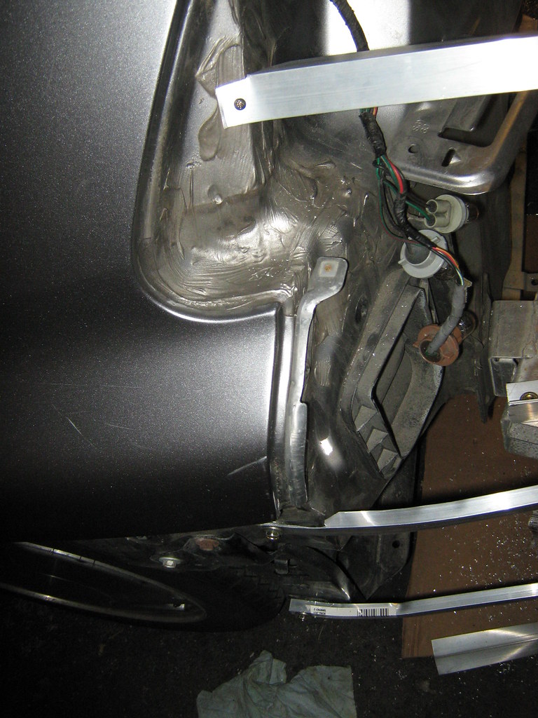
Three attachment points for each of the sides. The bottom two are made of aluminium channel, which is great stuff. You can bent the kind of radii you need for a boattail's sides and top without kinking. Unfortunately, I don't have a great way to attach it to the car without compromising its integrity at the car end.
Wheel skirts will fit over these attachement points.
I've used 20' of flats (great stuff, should have bought 50'), 16' of "U" channel, and 16' of "L" angle. Now I just have to skin this beast.
I'm not looking forward to that. I've been having trouble with my non-self tapping sheet metal screws breaking off while I try to tap with them, even though I drilled the right size pilot hole.
Also, coroplast and cardboard are all I have in stock. So coroplast it is. But that stuff requires a large number of fasteners to avoid tear-out. Lots of broken sheet metal screws tomorrow.
The tail extension makes the car 32" longer (i.e. this is the "short tail" version). Transom measures 32"x20", so I will have reduced my trailing wake from 57% of frontal area (iirc) to 22%. Good, but leaves room for improvement.
I leave Thursday morning, so if this tail doesn't pass a shakedown tomorrow night, it comes off and I drive a less interesting car the 1500mi round trip to Hybridfest. |
|
|
|
|
07-14-2010, 10:58 PM
|
#164 (permalink)
|
|
Left Lane Ecodriver
Join Date: Aug 2008
Location: Buffalo, NY, USA
Posts: 2,257
Thanks: 79
Thanked 287 Times in 200 Posts
|
Well, the good news is, an Insight tail extension is easy to remove. With my 13 attachment points, it took 8 minutes to remove the tail extension, and 14 minutes to bolt all the factory tail pieces on: bumper cover, taillights, wheel skirts. Even after I add details like illumination, we should be looking at under half an hour to switch it out. So this is the kind of thing you could hang in the garage most of the time, and install for long trips. Unless your commute is a long trip, in which case you'd best just leave it on, eh?
Also, I got my heat exchanger seat cover sewn together, and my 12V pump is wired through the rear wiper motor switch. I'll test that one out as I hit the road tomorrow. |
|
|
|
|
07-15-2010, 08:48 AM
|
#165 (permalink)
|
|
Administrator
Join Date: Dec 2007
Location: Germantown, WI
Posts: 11,203
Thanks: 2,501
Thanked 2,589 Times in 1,555 Posts
|
Will it be that easy to remove once its covered?
|
|
|
|
|
07-15-2010, 09:28 AM
|
#166 (permalink)
|
|
Left Lane Ecodriver
Join Date: Aug 2008
Location: Buffalo, NY, USA
Posts: 2,257
Thanks: 79
Thanked 287 Times in 200 Posts
|
Almost. The skin can extend under the wheel skirts without covering those two bolts on each side. The three bolts at the center will be accessible via the same access flap that lets me open the hatch. The ones at the taillights will be harder to access, though, as well as any attachment points I add on the underside.
|
|
|
|
|
07-15-2010, 10:42 AM
|
#167 (permalink)
|
|
Master EcoModder
Join Date: Jun 2008
Location: Chicago
Posts: 674
Thanks: 40
Thanked 39 Times in 27 Posts
|
Nice work! I think you should invest in some self tapping screws. I used them for my wheel skirts and they are fantastic. Wish I could remember the brand. Sorry about your life and stuff - Things for me have been a bit on the edge lately in this regard, and however it goes, I've just been thinking how it will just be another transition, another change in the pervasive cyclical nature of everything. Not warm and fuzzy for most people to think about, but it works for me. And my flasks.
__________________

|
|
|
|
|
07-18-2010, 07:27 PM
|
#168 (permalink)
|
|
Hypermiler Extraordinaire
Join Date: Oct 2008
Location: Deltona, FL
Posts: 22
Thanks: 1
Thanked 3 Times in 2 Posts
|
Quote:
Originally Posted by RobertSmalls

I jumpered the always-hot MCM pin B10 (white/red) to MCM pin A11 (pink/blue), which powers up everything on the IMA fuse. N.B. this does not include the inverter fan or DC/DC converter. The BCM and current sensor are powered and the battery fan should be live, and it keeps the SoC gauge accurate. That way I don't get a forced regen (wasted fuel) and a recalibration first thing in the morning.
 |
I must not have read this the first time correctly. So it seems that if I run 12v power to the MCM pin A11, the fan will be powered. Therefore, I can disconnect my taps into the fan wire and connect it there instead.
So MCM pin A11 is where the positive of the 12v should be tapped into, which one should the negative be connected to (and what color is it)?
Thanks so much for your help. Your boat tail project is really coming together! I wish I would have been able to make it up there to see it - hope you're having a great time!
|
|
|
|
|
07-19-2010, 05:40 PM
|
#169 (permalink)
|
|
Master EcoModder
Join Date: Jul 2008
Location: Cypress, TX
Posts: 331
Formula - '96 Firebird Formula/Trans-Am 90 day: 19.31 mpg (US)
Thanks: 8
Thanked 31 Times in 18 Posts
|
Quote:
Originally Posted by Wonderboy
Nice work! I think you should invest in some self tapping screws. I used them for my wheel skirts and they are fantastic. Wish I could remember the brand. Sorry about your life and stuff - Things for me have been a bit on the edge lately in this regard, and however it goes, I've just been thinking how it will just be another transition, another change in the pervasive cyclical nature of everything. Not warm and fuzzy for most people to think about, but it works for me. And my flasks.
|
Only problem with self tapping screws is they don't like to be removed and screwed back in a lot on a car's thin sheet metal.
__________________
 Lets see how far it can go
|
|
|
|
|
07-19-2010, 06:55 PM
|
#170 (permalink)
|
|
Left Lane Ecodriver
Join Date: Aug 2008
Location: Buffalo, NY, USA
Posts: 2,257
Thanks: 79
Thanked 287 Times in 200 Posts
|
Quote:
Originally Posted by Artric
I must not have read this the first time correctly. So it seems that if I run 12v power to the MCM pin A11, the fan will be powered. Therefore, I can disconnect my taps into the fan wire and connect it there instead.
So MCM pin A11 is where the positive of the 12v should be tapped into, which one should the negative be connected to (and what color is it)?
Thanks so much for your help. Your boat tail project is really coming together! I wish I would have been able to make it up there to see it - hope you're having a great time!
|
My 12V power supply's negative output wire references chassis ground. MCM pin A11 = power to the IMA system. It's connected to one leg of the IMA fuse, so if you power it up, you power everything on that fuse: the BCM's current sensor, SoC monitor, battery temperature monitor, and battery fan controls. But the battery fan won't come on unless one of your cells hits 140F, right? If the conditions inside your car are as punishing as I think they are, it's probably better to run the fan full time. What are your cabin temps, anyway?
Talking with Mr. Hansen this weekend, and reading Mr. Mik's posts at IC, lead me to question whether we should be topping off the cells nightly. Ask three different experts, get three different answers. I'll continue charging my well-balanced pack nightly, but I'll set the timer to try to get it no higher than 90% SoC if I can.
What did the NiMH EV1 and RAV4EV's chargers do? Top off every night, or stop at 90%?
|
|
|
|
|