 07-02-2013, 11:11 AM
|
#31 (permalink)
|
|
Master EcoModder
Join Date: Sep 2010
Location: Saskatoon, canada
Posts: 1,488
Thanks: 746
Thanked 565 Times in 447 Posts
|
Eagerly anticipating ..
Quote:
Originally Posted by MPaulHolmes

I finished building the MPPT charger. I'd go install it and test it out if it wasn't 119 outside right now.
|
I eagerly await pictures and data!
|
|
|

|
|
The Following User Says Thank You to thingstodo For This Useful Post:
|
|
 Today Today
|
|
|
|
 Other popular topics in this forum...
|
|
|
|
|
07-04-2013, 03:25 PM
|
#32 (permalink)
|
|
PaulH
Join Date: Feb 2008
Location: Maricopa, AZ (sort of. Actually outside of town)
Posts: 3,832
Thanks: 1,362
Thanked 1,202 Times in 765 Posts
|
We don't have the cell phone at the moment. T Mobile has it, but soon they'll say we can get a new phone. It's a long story. Soooo, no pictures until then! haha. Yesterday I installed 3 outlets outside next to the windows. Today I just hooked up the inverter to the house. We have a 12500btu or something like that window air conditioner that I plugged in, and the stupid inverter shut off due to overcurrent protection. But... Since I'm in charge of every stinking line of code on that thing, I just changed it so the hardware overcurrent protection clears itself automatically if it trips. That's the short term fix. I also ordered some higher amp current sensors to replace the LEM 50's I'm using at the moment. That will be safer, but I didn't want to wait for them to ship here.
Tomorrow I hook up the MPPT charger. So, today I'm running the batteries down a bit so the MPPT charger has something useful to do. I"m just waiting on some 2 gauge lugs that should arrive tomorrow!
Last edited by MPaulHolmes; 07-04-2013 at 03:49 PM..
|
|
|
|
|
The Following User Says Thank You to MPaulHolmes For This Useful Post:
|
|
|
07-04-2013, 08:58 PM
|
#33 (permalink)
|
|
Master EcoModder
Join Date: Sep 2010
Location: Saskatoon, canada
Posts: 1,488
Thanks: 746
Thanked 565 Times in 447 Posts
|
Starting induction motors
Quote:
Originally Posted by MPaulHolmes
...We have a 12500btu or something like that window air conditioner that I plugged in, and the stupid inverter shut off due to overcurrent protection. But... Since I'm in charge of every stinking line of code on that thing, I just changed it so the hardware overcurrent protection clears itself automatically if it trips. That's the short term fix...
|
If it's similar to my window air conditioner, there's a single phase induction motor in there that draws a very short peak of 6 times rated current (6X). It's connected to your compressor, so it starts up under load. It will trip generators .. that you would EXPECT to be big enough to handle starting up a 0.75 - 1.0 HP motor ... as well as inverters.
Instead of measuring the very high spike of current (which your power electronics will have to supply without melting) it may be more reasonable to put in a 'pre-charge resistor' or 'soft start' that limits the current on a few AC cycles when a SERIOUS overload is detected. Assume that the load is faulty - like a short circuit - and size the resistor - perhaps 6 ohms and 20W - to take a surge of 20 amps for 6 cycles (0.1 seconds). If you energize power electroincs - SCR, MOSFET - to 'bypass' the resistor at that point and the current is still pinned at 20A at that point, let the hardware over-current take it down. I realize that the resistor should be 120W, but that would be continuous. 20W should be a reasonable size and give you a decent safety factor if you limit the time.
This will cost you some board space and an additional SCR or MOSFET switching loss in efficiency. But it should save you 4 sizes on your MOSFETs for handling the surge start of an induction motor. It shouldn't mess up your hardware over-current ... too much ... I think ...
Just my opinion .. |
|
|
|
|
The Following User Says Thank You to thingstodo For This Useful Post:
|
|
|
07-05-2013, 01:20 AM
|
#34 (permalink)
|
|
PaulH
Join Date: Feb 2008
Location: Maricopa, AZ (sort of. Actually outside of town)
Posts: 3,832
Thanks: 1,362
Thanked 1,202 Times in 765 Posts
|
I am using some 600v 600amp chassis mount IGBTs that can handle like 2400 amps for a very short period, with a film cap that can handle short bursts of 10,000 amps. So, 6 x 11 amps (continuous is around 11 amps) is still safe. If I wasn't doing such brute force with big fat IGBTs, I would definitely do the resistor soft start.
|
|
|
|
|
The Following User Says Thank You to MPaulHolmes For This Useful Post:
|
|
|
07-05-2013, 09:14 PM
|
#35 (permalink)
|
|
Master EcoModder
Join Date: Sep 2010
Location: Saskatoon, canada
Posts: 1,488
Thanks: 746
Thanked 565 Times in 447 Posts
|
Drool, drool ...
Quote:
Originally Posted by MPaulHolmes
I am using some 600v 600amp chassis mount IGBTs that can handle like 2400 amps for a very short period, with a film cap that can handle short bursts of 10,000 amps...
|
WOW! - that's excessive even for paranoids like me! 
Did you buy the IGBTs and caps for something else, or did you get a *REALLY* good deal on them? That's the kind of hardware overkill that I'd like to use for an AC drive on an electric truck!
Of course, NOW I want to see the pictures even MORE ... electrical porn at it's best! |
|
|
|
|
The Following User Says Thank You to thingstodo For This Useful Post:
|
|
|
07-05-2013, 11:39 PM
|
#36 (permalink)
|
|
PaulH
Join Date: Feb 2008
Location: Maricopa, AZ (sort of. Actually outside of town)
Posts: 3,832
Thanks: 1,362
Thanked 1,202 Times in 765 Posts
|
haha. They had some IGBTs on Ebay. Tesseract (the guy that makes the Soliton1) was selling a bunch of 600v 600amp igbts in groups of 6 and 24, and I got 6 of them. They were like $65 each or something like that. The ring capacitor was like $150 or so from Future Electronics. I'm going to use 3 of them in the 3 phase controller that I need to just finish. They supposedly will do 400 amps at 400 volts continuously with good cooling.
|
|
|
|
|
The Following User Says Thank You to MPaulHolmes For This Useful Post:
|
|
|
07-07-2013, 05:33 PM
|
#37 (permalink)
|
|
PaulH
Join Date: Feb 2008
Location: Maricopa, AZ (sort of. Actually outside of town)
Posts: 3,832
Thanks: 1,362
Thanked 1,202 Times in 765 Posts
|
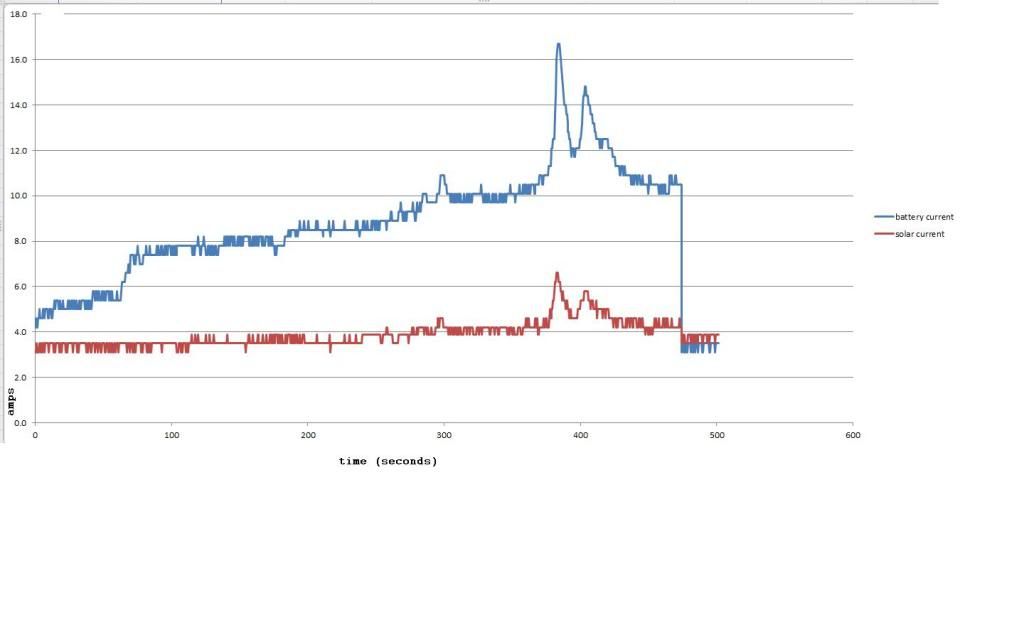
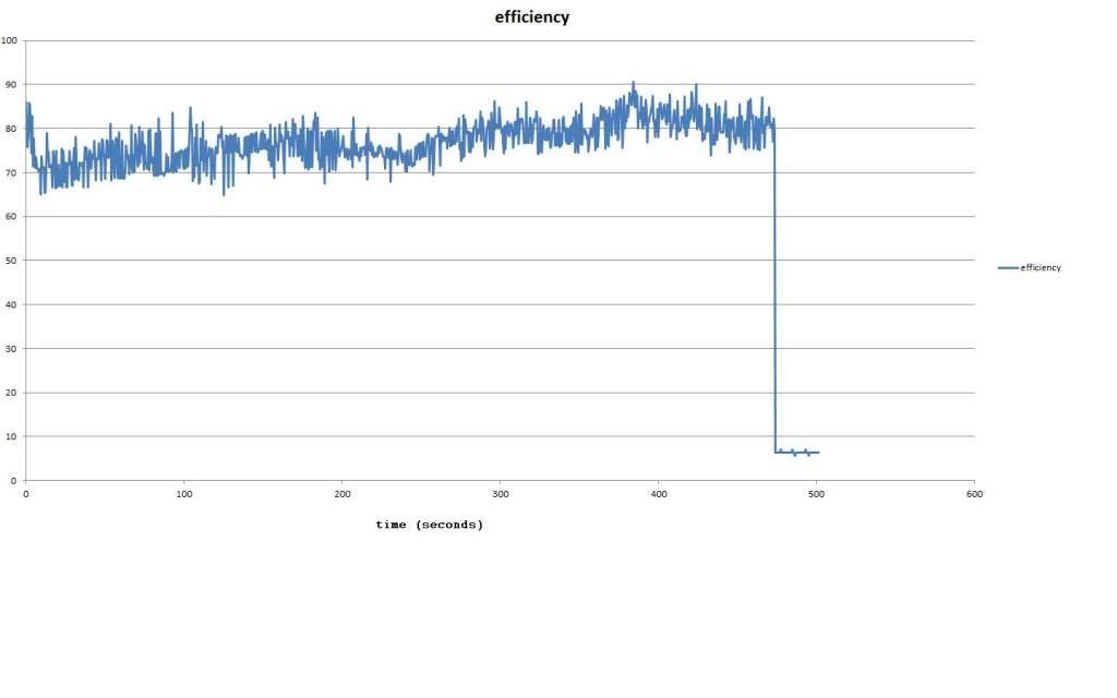
Hurray it works! It was a super cloudy day... The sun kept getting almost poking through, and then not at all, but I never did see my shadow! But an interesting time to try out the MPPT!!! Here are some graphs. The most interersting thing I found was, the power DIFFERENCE was almost constant between power in and power out. So, the efficiency goes up the brighter the sun is. At least that's what appears to be true at the moment. The x axis is seconds, y axis is whatever the label says! haha. The clouds were racing by, so the cloudiness changed significantly every 0.5 seconds or so.
battery current and solar current:
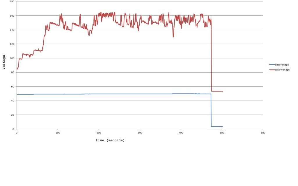
Battery and solar voltage:
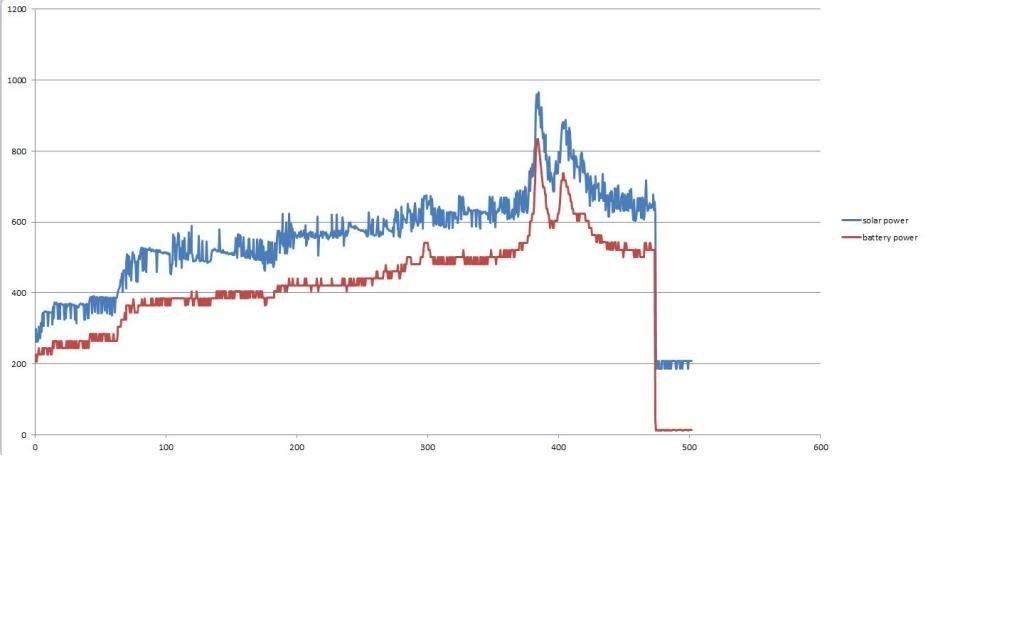
Battery power and solar power. Note: the batteries were receiving more power than was coming out of the panels! LOL. Just kidding. No need to move me to the unicorn corral...:
Power difference:
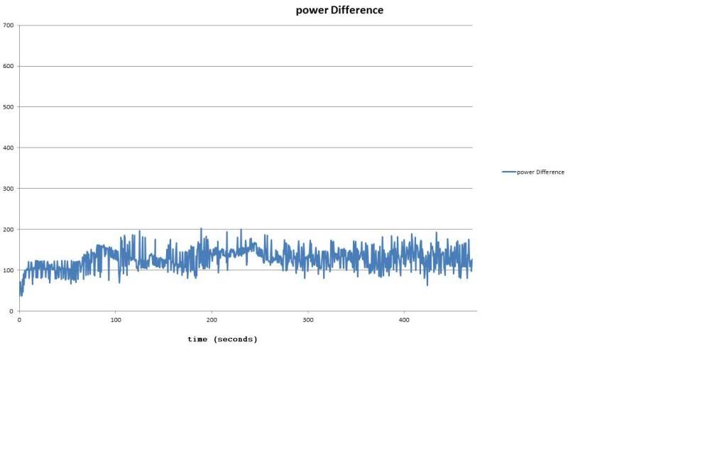
Efficiency. The efficiency went up as the sun would almost poke through. It peaked at around 90% when the sun was getting through almost. Then went back to stinking it up when the sun disappeared completely:
Last edited by MPaulHolmes; 07-07-2013 at 06:01 PM..
|
|
|
|
|
The Following User Says Thank You to MPaulHolmes For This Useful Post:
|
|
|
07-08-2013, 11:41 AM
|
#38 (permalink)
|
|
Master EcoModder
Join Date: Sep 2010
Location: Saskatoon, canada
Posts: 1,488
Thanks: 746
Thanked 565 Times in 447 Posts
|
Efficiency
It makes sense that part of the losses are overhead - switching, powering the electronics, that sort of thing. So the more power you put through, the lower the percentage of the overhead, the better your overall efficiency.
There SHOULD be a component that is a percentage of the power in - resistance losses in the IGBTs, traces, etc - anything to do with current.
Perhaps everything is oversized so much (well, I guess that part is not perhaps ... everything IS oversized so much) that the overhead losses are visible and the percentage losses are miniscule by comparison?
|
|
|
|
|
07-08-2013, 11:43 AM
|
#39 (permalink)
|
|
PaulH
Join Date: Feb 2008
Location: Maricopa, AZ (sort of. Actually outside of town)
Posts: 3,832
Thanks: 1,362
Thanked 1,202 Times in 765 Posts
|
I did some graphs of the power curve from solar panel voltage = open circuit to solar panel voltage = 48v (shorted to the batteries) starting just after the sun peeked over the panels until around 8am. Each period from open circuit to "short circuit" was about 40 seconds.
It's possible that the above curves werent' really the max power. They might be though. I think there may be some local maximums that aren't global power maximums.
|
|
|
|
|
07-08-2013, 04:23 PM
|
#40 (permalink)
|
|
PaulH
Join Date: Feb 2008
Location: Maricopa, AZ (sort of. Actually outside of town)
Posts: 3,832
Thanks: 1,362
Thanked 1,202 Times in 765 Posts
|
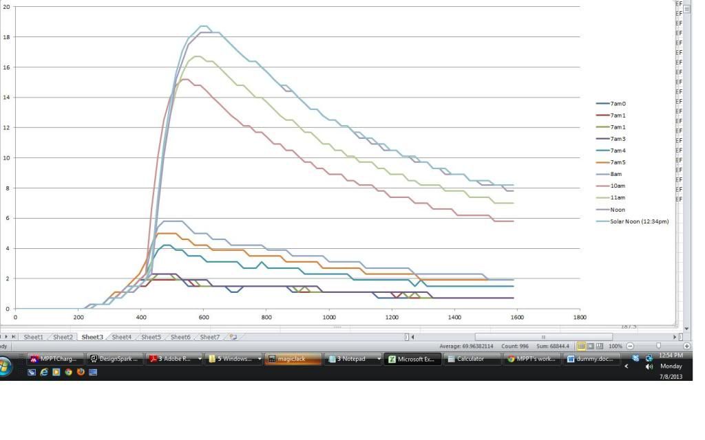
Here's a pretty cool graph that I made today by having the PWM duty cycle vary from 0 to 100% at different times throughout the day. The span across the whole duty cycle took 40 seconds each time. The input open circuit voltage was around 200v, and the output voltage was about 49v (48v battery bank that's mostly dead). The lowest curve was when the sun just started peeking over the panels. The highest curve was at solar noon (12:34pm) down here just south of Phoenix in Maricopa. Notice that to the right of the peak power point, there are occasional spots where it's a fake maximum power! Oh that makes me mad. This sort of illustrates the problem with algorithms that blindly search for any local maximum power point. It was 5 280w multicrystaline panels in series. I've got 3 more strings of 5 panels that I'll add to see how the curves change, but I think I need more batteries first. That's a lot of amps at 48v:
|
|
|
|
|
The Following User Says Thank You to MPaulHolmes For This Useful Post:
|
|
|


