 01-08-2014, 10:25 PM
|
#1 (permalink)
|
|
Human Environmentalist
Join Date: Aug 2010
Location: Oregon
Posts: 13,008
Thanks: 4,373
Thanked 4,544 Times in 3,493 Posts
|
Supercapacitor Battery Replacement
My quest to replace conventional lead-acid car batteries with supercapacitors was inspired by this thread. I have started my project and will share all of my findings with as much detail as possible, and hopefully get some answers to lingering questions.
Questions:
1. How do the energy losses of charging/discharging a supercapacitor compare to lead-acid batteries or LiFePo4 batteries?
Lead-acid batteries are approximately 50% efficient considering the charge/discharge losses. The losses are not linear, and increase as the battery nears full capacity. This is particularly unfortunate as lead-acid batteries need to be maintained at full capacity to avoid sulfation and damage.
LiFePo4 batteries are 90% efficient in the charge/discharge cycle.
Super capacitors are 90-99% efficient at storing and releasing a charge. The superior efficiency is obtained because a capacitor is merely storing a static charge, whereas the lead-acid battery relies on a chemical reaction. Efficiency is reduced at high frequency pulsing of charge/discharge, and at higher currents. A steady, low current draw will approach 99% efficiency.
2. How does the self-discharge of a supercapacitor compare to the self-discharge of lead-acid or LiFePo4 batteries?
There is some self-discharge, although it's difficult to quantify. The majority of the discharge occurs towards peak voltage. The effect is more pronounced due to the lower charge capacity and the corresponding drop in voltage. Where a battery may self-discharge and loose overall capacity but maintain voltage, a capacitor looses capacity by loosing voltage.
3. What is the typical minimum voltage that a modern vehicle needs to maintain functions such as radio presets, clock, etc and still be able to start?
The motorcycle requires 10v on my 400 farad capacitor bank to start. It requires 8.5v to run all computer functions and display. Memory is lost at voltages below 6v.
4. How many amps can be drawn and for what duration can be tolerated by the relatively thin terminals of the supercapacitors?
Unknown. Resistance is a function of material, diameter, and length. The very short copper leads of the capacitor can likely handle hundreds of amps without melting. So far, I've only gone up to 200 amps an 12 AWG wire, but I plan to push them harder.
5. What is the expected operational lifetime of a supercapacitor battery?
Likely the life of the vehicle, assuming a balance circuit is used and under-hood temps do not get too hot. Life is a function of voltage and heat multiplied by the amount of time the capacitor is held under those conditions. Maximum operating temperature is 150F (65C)
Quote:
|
To give one example, a 15% reduction in rated capacitance and a 40% increase in rated resistance may occur for an ultracapacitor held at 2.5 V after 88,000 hrs at 25 o C. The plots, along with the fact that the influence of temperature has a doubling effect for every 10 o C, can be used to predict the expected performance change for a variety of conditions.
|
6. What is the optimal balance circuit for automotive applications?
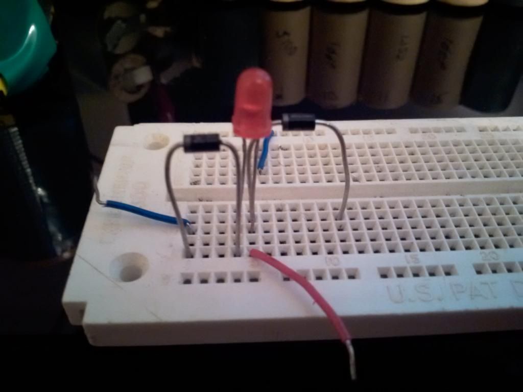
Wiring a single diode with a 0.5v drop in series with a single LED with a 1.8v drop is ideal to trim voltage. This is an example of passive balancing. There are also active balance circuits that compares the voltage of 2 capacitors and then drains a little of the voltage in the higher voltage cap into the lower voltage one until they are in balance.
7. In the long run, can I save money by using a capacitor/LiFePo4 combo instead of buying lead-acid batteries every 7 years or so?
I'll let you know in 7 years. There doesn't seem to be much info available regarding LiFePo4 batteries in automotive use. One concern is that charging them in sub-freezing temperatures can cause permanent damage.
Last edited by redpoint5; 10-03-2014 at 02:37 PM..
|
|
|

|
|
The Following 3 Users Say Thank You to redpoint5 For This Useful Post:
|
|
 Today Today
|
|
|
|
 Other popular topics in this forum...
|
|
|
|
 01-08-2014, 10:57 PM
|
#2 (permalink)
|
|
Master EcoModder
Join Date: Jul 2008
Location: Langley, BC
Posts: 1,228
Fusion - '16 Ford Fusion Hybrid SE
Thanks: 190
Thanked 275 Times in 168 Posts
|
I too was fascinated by that thread. Unfortunately I had JUST put a new battery in my wife's Toyota Matrix.
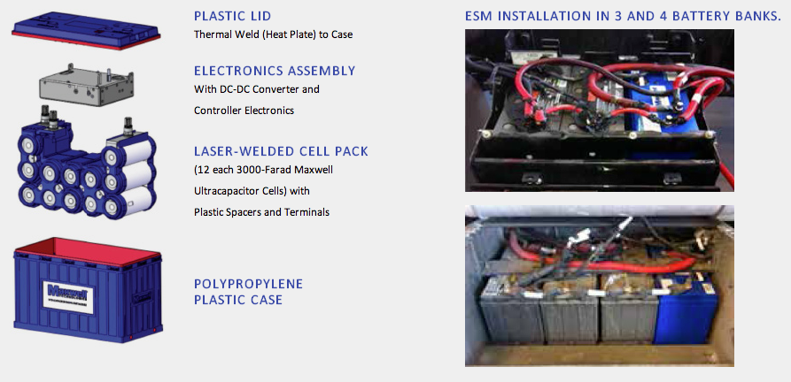
Maxwell Technologies sells a group 31 ultra-capacitor for heavy duty trucks. Normally, HD trucks have four 12V lead acid batteries (wired in parallel for 12 volts and 3000-3600 CCA), but apparently in the prairies in the ultra-cold weather they are trying three batteries with one capacitor unit with massive success.
Maxwell Technologies Engine Start Module: for saving money, it's the fleet service manager's choice
Even if the batteries get discharged down to 9 volts, a single capacitor unit with still start the truck.

I would love to build a cheap/tiny lithium/cap unit to try in my motorcycle, although nothing is wrong with the battery it has in it. |
|
|

|
|
The Following 3 Users Say Thank You to mechman600 For This Useful Post:
|
|
 01-08-2014, 10:59 PM
|
#3 (permalink)
|
|
Master EcoModder
Join Date: Jul 2008
Location: Langley, BC
Posts: 1,228
Fusion - '16 Ford Fusion Hybrid SE
Thanks: 190
Thanked 275 Times in 168 Posts
|
Quote:
Originally Posted by redpoint5

5. What is the expected operational lifetime of a supercapacitor battery?
|
According to the Maxwell Technologies website, 1000,000 cycles. That'll do. |
|
|

|
|
The Following 2 Users Say Thank You to mechman600 For This Useful Post:
|
|
 01-08-2014, 11:13 PM
|
#4 (permalink)
|
|
Human Environmentalist
Join Date: Aug 2010
Location: Oregon
Posts: 13,008
Thanks: 4,373
Thanked 4,544 Times in 3,493 Posts
|
First Supercapacitor Battery
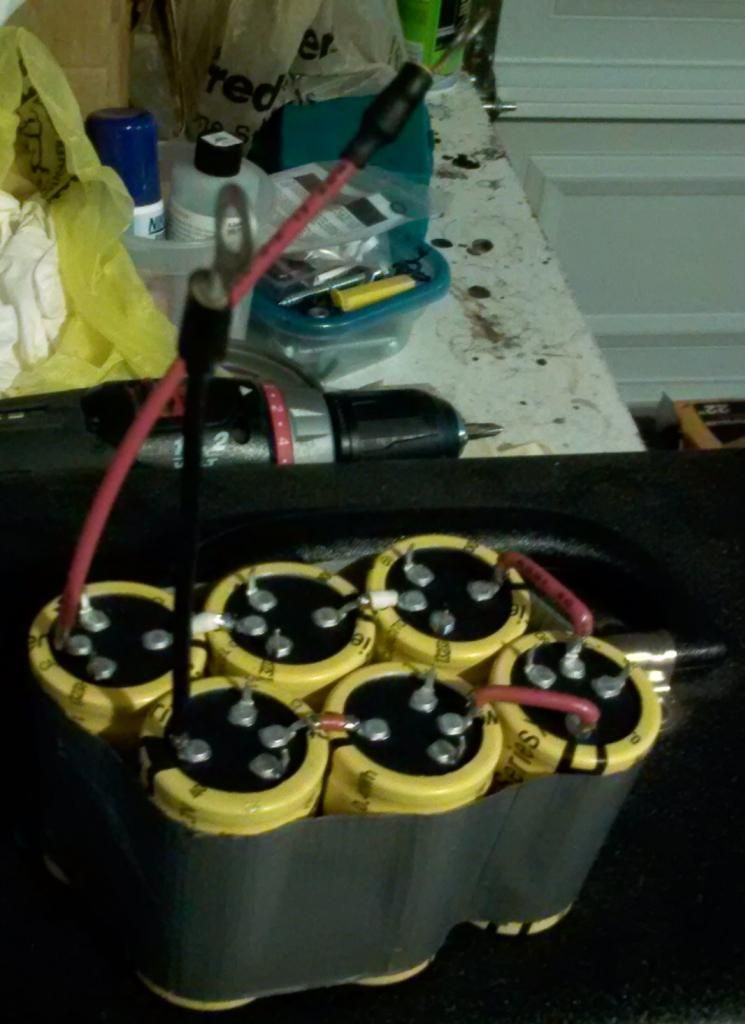
I purchased 6x 2.7 volt 400 farad supercapacitors from Digikey for $77.66 including shipping  Above 400F, the price of the capacitors skyrocket.
Trying to keep cost down as much as possible, I used 12awg wire that was already on hand to create the very short series connections and the 6" positive and negative leads. The positive and negative wires were cut to slightly different lengths to reduce the chance of accidentally touching them together.
I wonder how many amps I can safely push through these 6" 12AWG wires?

After soldering everything together and using duct tape to crudely hold the 6 cells together, I charged the whole series of capacitors up to 13.5v using an RC battery charger. Initially the charger delivered 7+ amps, but as voltage of the capacitor series grew, the amps plummeted until I cut charging at about 30mA. While the charge took place, I used a voltmeter to periodically check each cell for balance. At full charge, the cells maintained extremely close balance.
The Honda Rancher ATV was the first vehicle tested. It has a parasitic electrical load of 0.5mA, which is extremely low. The capacitor series alone should be able to replace the battery. Since it has a pull start as a backup, there is no danger in depleting the capacitors.
After removing the suspected weak battery and replacing it with the capacitors, I turned the ignition on, verified 13v, and hit the starter... click. That was all I heard. The voltage held steady and my ammeter registered a max draw of 4 amps. It looks like what my dad thought was a weak battery was instead a problem with one of the brushes on the starter motor. I pull-started the ATV and watched the capacitor voltage climb to 14.5v and hold steady.
Since I didn't have time to get the ATV working to test the ability to run on capacitors only, I moved on to Lafawnda (the Honda motorcycle). She had a measly 1.25mA parasitic load. Another great candidate for battery replacement, especially since she is a performance machine and responds well to loosing just a few pounds of weight.
I accidentally blew the fuse on my RC charger, so I attempted to start Lafawnda on the 10v remaining charge from the capacitors.
Well, she started with just 10v and drew a peak of 77 amps! I don't think it would have started with much less than 10v.
I have measured my Dodge/Cummins at over 400A peak when cranking, and I'm not brave enough to even put the capacitors in parallel with the 2 weak starting batteries for fear of melting the leads or hurting the capacitors. I might build up the courage after completing more testing, including starting the TSX.
Last edited by redpoint5; 06-29-2014 at 01:35 AM..
|
|
|

|
|
The Following 8 Users Say Thank You to redpoint5 For This Useful Post:
|
|
 01-08-2014, 11:24 PM
|
#5 (permalink)
|
|
Master EcoModder
Join Date: Jul 2008
Location: Langley, BC
Posts: 1,228
Fusion - '16 Ford Fusion Hybrid SE
Thanks: 190
Thanked 275 Times in 168 Posts
|
Quote:
Originally Posted by redpoint5

I wonder how many amps I can safely push through these 6" 12AWG wires?
|
Probably about 77 amps...lol. I would go bigger - even 10 AWG would make a significant difference.
Capacitors self-discharge much quicker than lead acid/lithium. Some sort of small four cell lithium backup pack with a low voltage cutoff (at 2.5 volts per cell to avoid lithium batricide if they discharge too far) would be the ticket. If you bottom balance four lithiums, a BMS will not be necessary either.
Nice work! |
|
|

|
 01-08-2014, 11:44 PM
|
#6 (permalink)
|
|
Human Environmentalist
Join Date: Aug 2010
Location: Oregon
Posts: 13,008
Thanks: 4,373
Thanked 4,544 Times in 3,493 Posts
|
Balance Circuit
The capacitors are still within 0.01v of each other after a dozen or so charge/discharge cycles, so I haven't implemented a balance circuit yet.
Laserhacker references diode part #1N4001, which has a forward voltage drop of roughly 0.5v. The red led has a voltage drop of about 1.8v, so combined the circuit should limit each capacitor to 2.3v. Multiply that by 6 capacitors, and the circuit will slowly bleed off anything above 13.8v. Since the capacitors are rated for 2.7v, and automotive alternators typically charge to 14.5v, it seems a waste to bleed off the "extra" voltage.
I tested various LED colors for measured voltage drop, and will attempt to build a balance circuit that limits individual capacitor voltages to 2.6v instead of 2.3v.
Here are the results of the forward voltage drop for various diodes:
Diode - 0.52v
Red diffused LED - 1.8v
Red clear LED - 1.64v
Green diffused LED - 1.79v
Orange diffused LED - 1.61v
Yellow diffused LED - 1.7v
Yellow clear LED - 1.79v
If I place 2 diodes and 1 orange diffused LED in series, I get a 2.65 volt drop. When I get a chance, I will test various configurations for their performance at balancing the capacitors at various states of charge.


Last edited by redpoint5; 01-09-2014 at 12:52 AM..
|
|
|

|
 01-09-2014, 12:04 AM
|
#7 (permalink)
|
|
Human Environmentalist
Join Date: Aug 2010
Location: Oregon
Posts: 13,008
Thanks: 4,373
Thanked 4,544 Times in 3,493 Posts
|
Quote:
Originally Posted by mechman600

Probably about 77 amps...lol. I would go bigger - even 10 AWG would make a significant difference.
Capacitors self-discharge much quicker than lead acid/lithium. Some sort of small four cell lithium backup pack with a low voltage cutoff (at 2.5 volts per cell to avoid lithium batricide if they discharge too far) would be the ticket. If you bottom balance four lithiums, a BMS will not be necessary either.
Nice work!
|
Initially I had purchased 10AWG wire since it was the largest size carried by Norvac Electronics. It was $16 for 20ft though! I returned the wire after finding heaps of 12AWG wire in my Dad's garage. I figure I can run double strands of 12AWG if it isn't thick enough.
It seems that wire gauge isn't the only limiting factor with these capacitors. The terminals themselves are very small, much smaller diameter than the 12AWG wire attached to it. Not only that, but I assume they are aluminum and don't conduct as well as the copper wires. Perhaps these small terminals are at more risk of melting down than the short copper leads?
I'm hoping there is less chance of accidentally welding something since the thin gauge terminals and wires are used.
Next I will buy a LiFePo4 4.2AH battery and test it combined with the supercapacitors. I'm not in a hurry to replace batteries that haven't yet failed, so I don't expect to use it as a permanent replacement for a while. |
|
|

|
|
The Following User Says Thank You to redpoint5 For This Useful Post:
|
|
 01-09-2014, 04:15 AM
|
#8 (permalink)
|
|
EcoModding Apprentice
Join Date: Aug 2013
Location: Dorset UK
Posts: 106
Thanks: 1
Thanked 56 Times in 29 Posts
|
Are there safety issues with electrocuting yourself out the workshop roof with these things?
Please educate me as I always thought capacitors were potentially dangerous things...... If safe enough then I am onto building a set up for my Lupo 3L
__________________
Black Lupo 3L 1.2tdi Manual converted the windsurfing bus!
Kermit the Lupo 3L 1.2 Tdi with a current mpg record of 114mpg (imperial) Now sold
G1 JDM Insight I hate the ride but love the quirkiness
|
|
|

|
 01-09-2014, 06:36 AM
|
#9 (permalink)
|
|
Master EcoModder
Join Date: Sep 2009
Posts: 5,927
Thanks: 877
Thanked 2,024 Times in 1,304 Posts
|
I've had two capacitors go bad on my home AC units. The heating and air gent who diagnosed and fixed them told me that since PCBs were outlawed in the US the failure rate of capacitors has risen dramatically.
Think I'll wait awhile before chaning my system. Also had one go bad on my ceiling fan that I replaced myself.That one go pretty hot and the case swelled up and it almost melted, or at least melted enough to make it very visible.
regards
Mech
|
|
|

|
 01-09-2014, 08:27 AM
|
#10 (permalink)
|
|
Master EcoModder
Join Date: Apr 2013
Location: World
Posts: 385
Thanks: 82
Thanked 82 Times in 67 Posts
|
Answers starting from the OP on:
1. Capacitors will take and give up charge with high 90's% efficiency. Chemical cell batteries are closer to 60-70% efficiency at best. i.e 0.7 X 0.7 = 0.49 or <49% for the cycle with chemical cells vs closer to 95% for the capacitors. That's ignoring any loss anywhere else.
2. Self discharge? On Maxwell or other manufacturer's site somewhere? I'm not sure that they do self discharge faster than Lead acid (Where to? Across the charged plates?) but rather don't hold as much charge in the first place, and have a steeper drop off in voltage for a given discharge.
3. A minimum of 10V seems to be fine. As you have seen, engaging the starter will cause a battery's voltage to fall to ~ that anyway and is routine.
4. Is there a current draw spec. for the capacitors available from the manufacturer?
12g wire has a resistance of ~1.8 Ohms/1000ft. Does that help?
Perhaps a bench test with a variable resistance/load while measuring the current drawn and observe the temp. of the wires?
5. Lifetime ^.
6. ?
7. Probably not.
You can work out how much cranking time you have in your capacitors by working out the difference between the charge stored at 10V and at 14V (or whatever your alternator charges at). With your measured discharge current while starting, ~efficiency (try 95%), 1 Coulomb is 1A supplied for 1 sec and you can find your cranking time.
Also consider that the charge stored across a capacitance is non-linearly proportional to the voltage; a capacitor charged to 10V is holding less than 10/14 of it's charge at 14V. The Maxwell Engine Start Module incorporates a DC-DC converter. 12 2.7V capacitors will charge to 32V. If the truck system is 12V (14.2V) there is a step up and step down occurring within the Start Module. I expect that's why the Mazda system - which will also use DC-DC conversion - uses 24V to charge the capacitors. (Comment in the linked thread in the OP.)
|
|
|

|
|
The Following 2 Users Say Thank You to Occasionally6 For This Useful Post:
|
|
|