 06-02-2015, 09:03 PM
|
#11 (permalink)
|
|
Master EcoModder
Join Date: Aug 2012
Location: northwest of normal
Posts: 29,044
Thanks: 8,246
Thanked 9,008 Times in 7,442 Posts
|
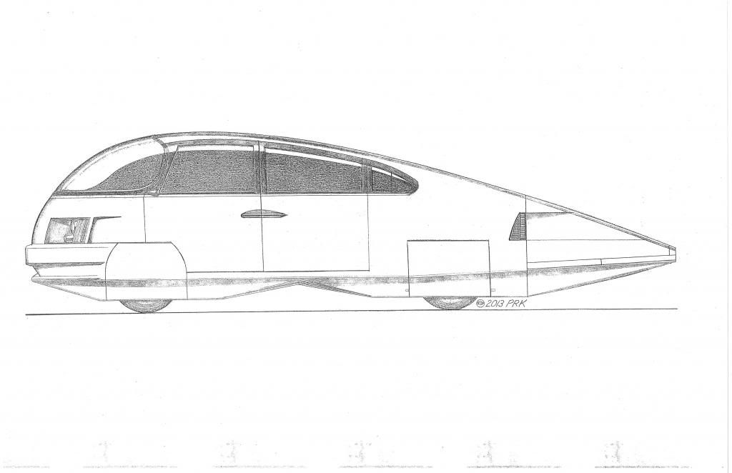
You may be hampered by lack of overhang to work with, but more angled is better. And as much so, between the wheels. Looked at your way, the angle becomes the edge of a downward-facing box.
Do you think you can fit better to the tire with the open or closed face of the fairing?
|
|
|

|
 Today Today
|
|
|
|
 Other popular topics in this forum...
|
|
|
|
 06-02-2015, 09:57 PM
|
#12 (permalink)
|
|
Master EcoModder
Join Date: Apr 2012
Location: Evensville, TN
Posts: 676
Thanks: 237
Thanked 580 Times in 322 Posts
|
Freebeard,
The very front of the Tacoma has fairly minimal overhang and one side on the back has the exhaust pipe to contend with. I can increase the angle some though. You are right, my posted design is more of a open box, obviously far from ideal and much less sophisticated than the design on the AST or on the solar cars Aerohead posted. The back piece is only acting like a boat tail in one dimension, not two since the bottom is open. Given the open bottom allowing boat tailing in only one dimension, does the upward angle on the back fairing matter much? I could see the benefit to the upward angle on the back much easier if it had a closed bottom.
I could get much closer to the tire with the open end of the fairing, however since I have two sets of tires (on-road and off-road) of different sizes the fit really can't be perfect on the 31.7” on-road tires or the 33.4” off-road tires won't fit. The reasons I designed the closed faces next to the tires on the back fairings was to allow a small radius at that transition, to keep from creating a parachute when I turn the wheels, to make it easier to strike objects with the fairing without hanging up while going forward, and to allow the rear fairings to act as a functional mud-flap.
|
|
|

|
 06-03-2015, 12:02 AM
|
#13 (permalink)
|
|
Master EcoModder
Join Date: Aug 2012
Location: northwest of normal
Posts: 29,044
Thanks: 8,246
Thanked 9,008 Times in 7,442 Posts
|
There's only so much you can do at the front; but behind the front and in front of the rear wheel (and maybe at the back) take a piece of belting maybe 3 to 3.5ft long and clamp 'square' corners in the middle and cut the necessary taper on the tails. Then lap or fold the ends and rivet them about half-way to the wheel end, leaving a triangle hole to drain mud and ice-melt. Three points of attachment minimum, two at the wheel and one at the end.
That's sort of your and my ideas mashed together.
|
|
|

|
|
The Following User Says Thank You to freebeard For This Useful Post:
|
|
 06-03-2015, 06:48 PM
|
#14 (permalink)
|
|
Master EcoModder
Join Date: Jan 2008
Location: Sanger,Texas,U.S.A.
Posts: 16,420
Thanks: 24,474
Thanked 7,410 Times in 4,800 Posts
|
renderings
Quote:
Originally Posted by aardvarcus

Thank you everyone for your input and feedback.
I have previously sucessfully used conveyor belt (baling belt from TSC) for my front air dam. ( http://ecomodder.com/forum/showthrea...tml#post453541) It works very well and is quite stiff when it is curved in one dimension and rigidly fixed at the top. It does not deflect even with my relatively minimal curve on my air dam on highway/interstate speeds, so in even sharper curves I would not worry about wind deflecting the fairing. The conveyor belt does have enough give that it would give if it contacted a rigid object to deflect and bounce back, so no real need for hinges.
I did some rough sketching in Sketch-Up, and attached some renderings of a front tire and fairings. Hopefully this will be more clear than my poor sketches in the first post. |
*They'd be worth trying,but I'd be concerned,that without full wheel skirts on first,or very close wheel/wheel-arch seals and full wheel covers,that the transverse jet of air which blows out of the wheelhouse would ruin the flow in the area that the fairings would be operating in.
This flow is perpendicular to the main airstream.It really shows up in rain.
*The fairings have got to have a fighting chance if they're gonna do you any good.
http://40.media.tumblr.com/d57a55177...ho1_r1_500.png
__________________
Photobucket album: http://s1271.photobucket.com/albums/jj622/aerohead2/
|
|
|

|
|
The Following 3 Users Say Thank You to aerohead For This Useful Post:
|
|
 06-03-2015, 08:59 PM
|
#15 (permalink)
|
|
Master EcoModder
Join Date: Aug 2012
Location: northwest of normal
Posts: 29,044
Thanks: 8,246
Thanked 9,008 Times in 7,442 Posts
|
Must be nice having that kind of fineness ratio to work with.
But I think it would be possible to make that shape of belting instead of aluminum; with a bracket to force two sharp folds at the wheel end, with the free ends rolled onto each other to make a transition to a half-circular end. With a triangular hole at the bottom as a strain relief.
|
|
|

|
 06-08-2015, 06:59 PM
|
#16 (permalink)
|
|
Master EcoModder
Join Date: Jan 2008
Location: Sanger,Texas,U.S.A.
Posts: 16,420
Thanks: 24,474
Thanked 7,410 Times in 4,800 Posts
|
Goro Tamai
I went back through Tamai's book,'The Cutting Edge'. The research demonstrated a 70% drag reduction for the solar car's wheel system when the full,swept,fairings were employed,in spite of their frontal area increase.
One of Hucho's examples showed a 53.3% drag increase when wheel systems were added to a low-drag body.
Tamai's work suggests that this penalty could be cut to 16%.That's well worth going after.
__________________
Photobucket album: http://s1271.photobucket.com/albums/jj622/aerohead2/
|
|
|

|
|
The Following User Says Thank You to aerohead For This Useful Post:
|
|
 04-20-2016, 03:08 AM
|
#17 (permalink)
|
|
Master EcoModder
Join Date: Aug 2012
Location: northwest of normal
Posts: 29,044
Thanks: 8,246
Thanked 9,008 Times in 7,442 Posts
|
Now I'm looking at the hand-waving in Permalink #13 and 15, and I wonder what I was going on about.  |
|
|

|
 04-21-2016, 04:32 PM
|
#18 (permalink)
|
|
Master EcoModder
Join Date: Jan 2008
Location: Sanger,Texas,U.S.A.
Posts: 16,420
Thanks: 24,474
Thanked 7,410 Times in 4,800 Posts
|
laminar
Quote:
Originally Posted by Frank Lee

Is that for true laminar flow, which we aren't going to get on the street anyway?
|
Frank,the solar racers which use them are only laminar on their bodies up to their maximum cross-section,where the 1st minimum pressure occurs,and boundary layer jumps to a turbulent boundary layer.The wheel fairings up front would behave the same way.The rear fairings would be potentially running in the turbulence of the front wheel fairings.
So we shouldn't consider them laminar unless they were running solo,on a closed-course,on a windless day,at very low velocity.
I think some of the cars have been tested upwards of 90-mph (Honda Dream-2)
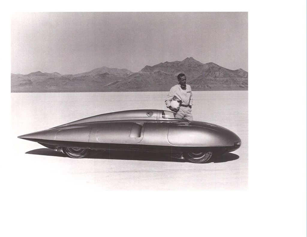
The Cd 0.12 1957 MG EX 181 would not be a laminar car,running 250-mph.
Come September 9th I hope to have some definitive data,as the T-100 will sport completely illegal- depth wheel fairings in the wind tunnel, which simulate 'active' fairings deployed only above 45-mph highway driving.
PS: Also,Hucho tells us in his books that the only way for a passenger car to approach Cd 0.08,is to further integrate the wheels into the body.Which implies the use of fairings.
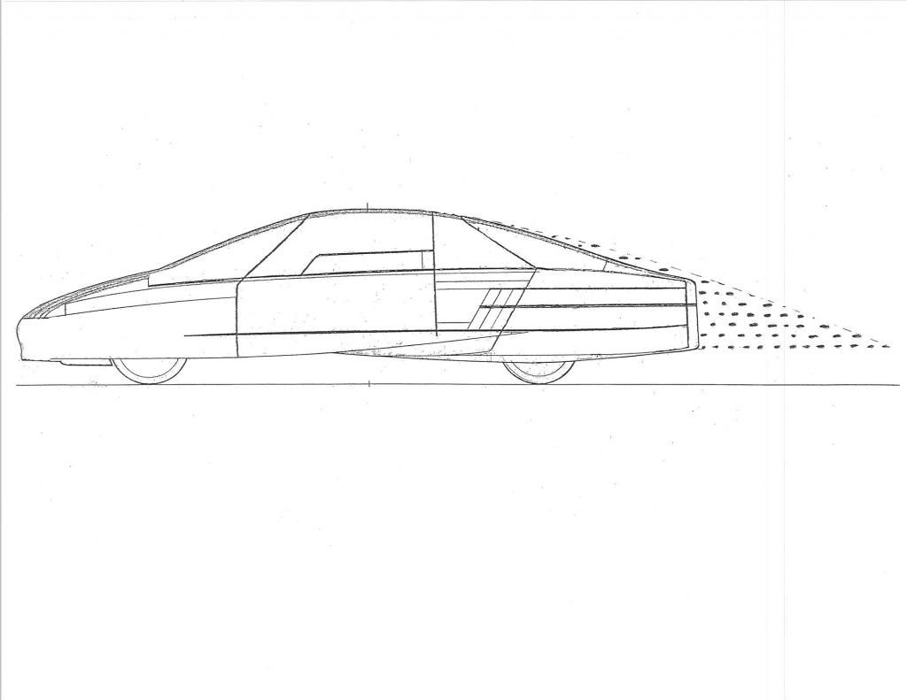
Ford got to Cd 0.137 with their 1985 Prove-V by bringing the wheels into the body and fairing them a bit.They could go lower with active devices.
__________________
Photobucket album: http://s1271.photobucket.com/albums/jj622/aerohead2/
Last edited by aerohead; 04-21-2016 at 04:44 PM..
|
|
|

|
|
The Following 3 Users Say Thank You to aerohead For This Useful Post:
|
|
 04-22-2016, 02:55 PM
|
#19 (permalink)
|
|
Master EcoModder
Join Date: Jan 2008
Location: Sanger,Texas,U.S.A.
Posts: 16,420
Thanks: 24,474
Thanked 7,410 Times in 4,800 Posts
|
wheel drag
Here,in this image provided by Hucho,you can see from the upper two images that drag increases from Cd 0.091,to 0.14 when the wheels are added.A 53.8% drag increase.
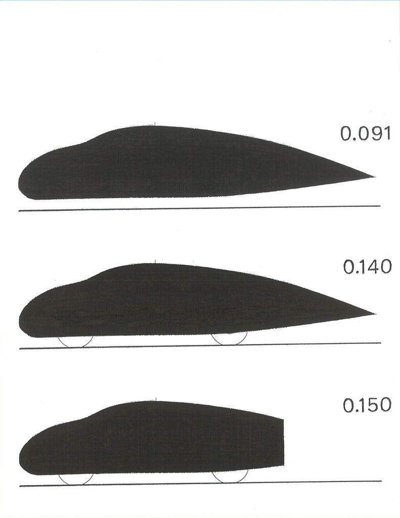
The 1987 GM Sunraycer has been reported at as high as Cd 0.143,and as low as Cd 0.089 with full wheel fairings.
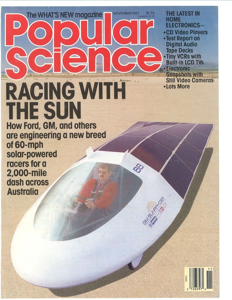
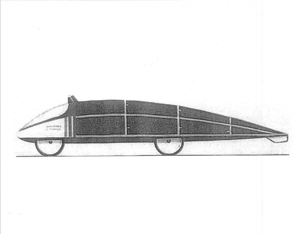
In his book 'The Leading Edge',Goro Tamai reported that full wheel fairings could reduce wheel drag by up to 80%.
Honda reported Cd 0.10 for their fully-faired (but exposed-wheel) Dream-2 solar racer

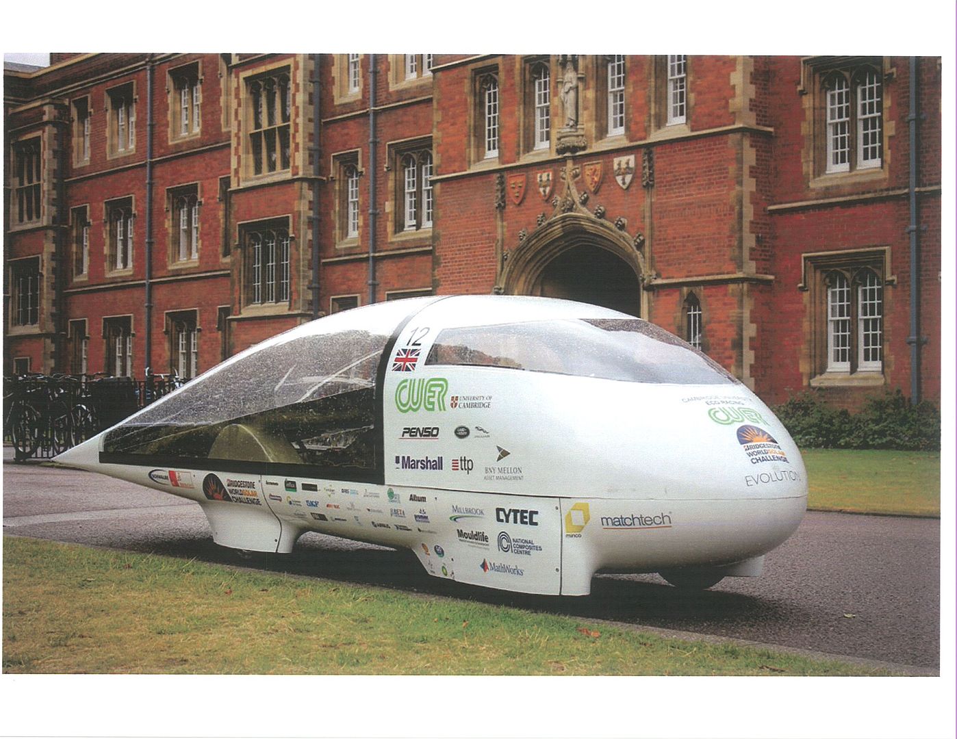
The Cambridge University CUER also reports Cd 0.10
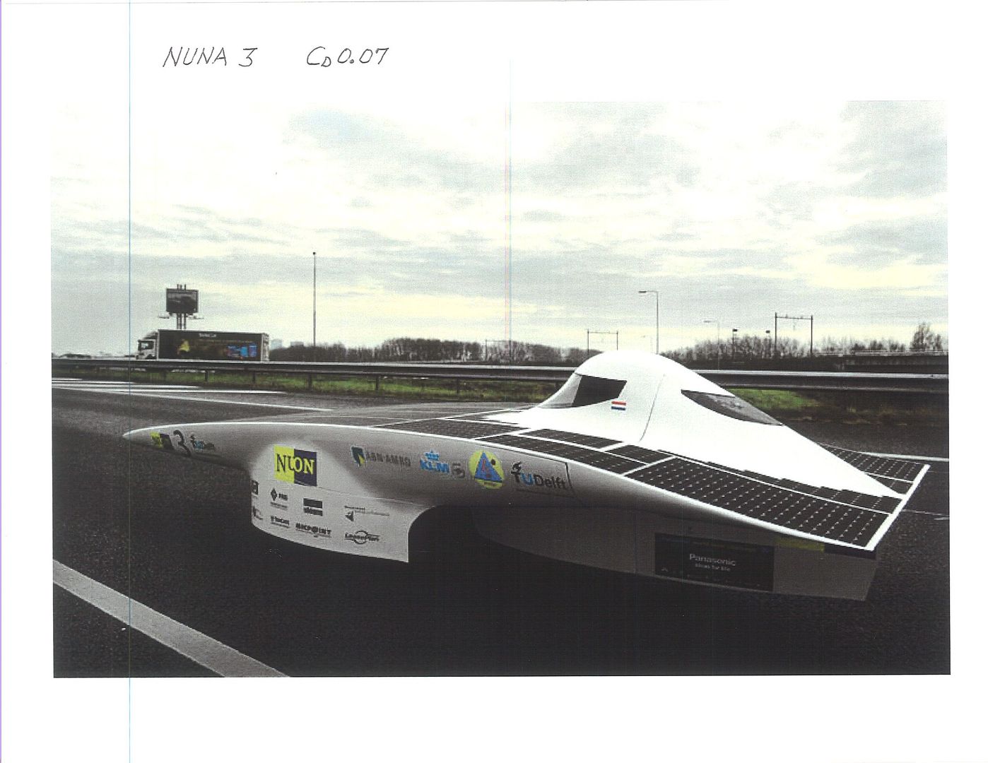
NUON NUNA-3 thru 7 report Cd 0.07
__________________
Photobucket album: http://s1271.photobucket.com/albums/jj622/aerohead2/
|
|
|

|
|
The Following User Says Thank You to aerohead For This Useful Post:
|
|
|