Go Back   EcoModder Forum > EcoModding > Aerodynamics
Register Now
 Register Now
 

Reply  Post New Thread
 
Submit Tools LinkBack Thread Tools
Old 01-29-2022, 07:38 PM   #1 (permalink)
HPV Tussie
 
Join Date: Dec 2021
Location: Germany
Posts: 81
Thanks: 6
Thanked 63 Times in 36 Posts
Aerodynamic aspects of an old GoOne 3 velomobile

Well, as already mentioned, this thread is on my old GoOne3 and a discussion on possibilities for aerodynamic improvements.
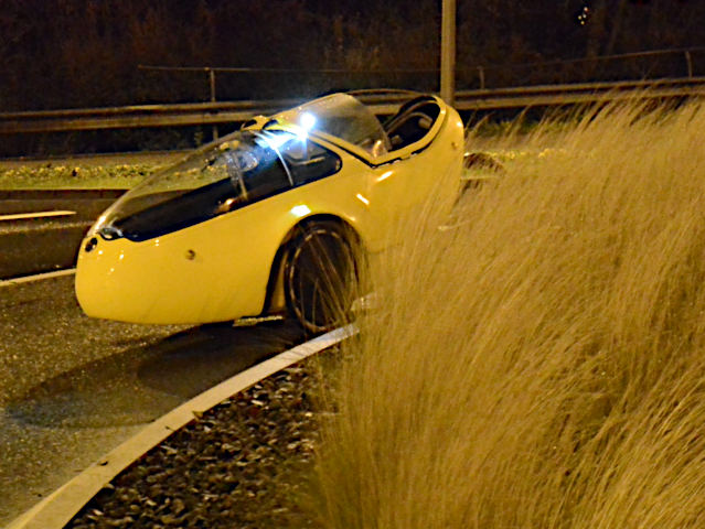
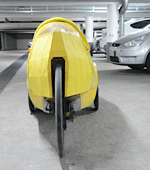
This vehicle:


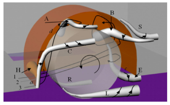
It is actually an iconic design, after meanwhile more than 20 years still appealing to many people, and its most characteristic feature possibly is also its largest aerodynamic drawback: the free standing back wheel, and the resulting huge wake. The bike is roughly as fast as a race bike. Which translates into a Cd estimate of roughly 0.37 using a reasonable estimate on front surface (and the Kreuzotter calculator).

Before i come to my attempts on my bike a few pics of successful modifications:

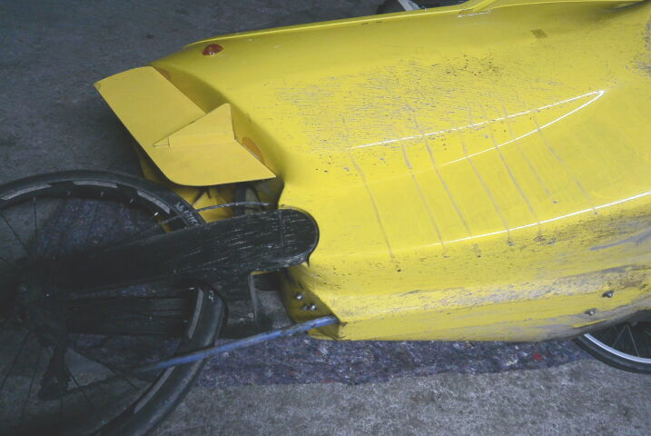
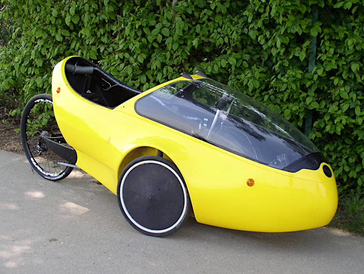
a) race trim by Daniel Fenn


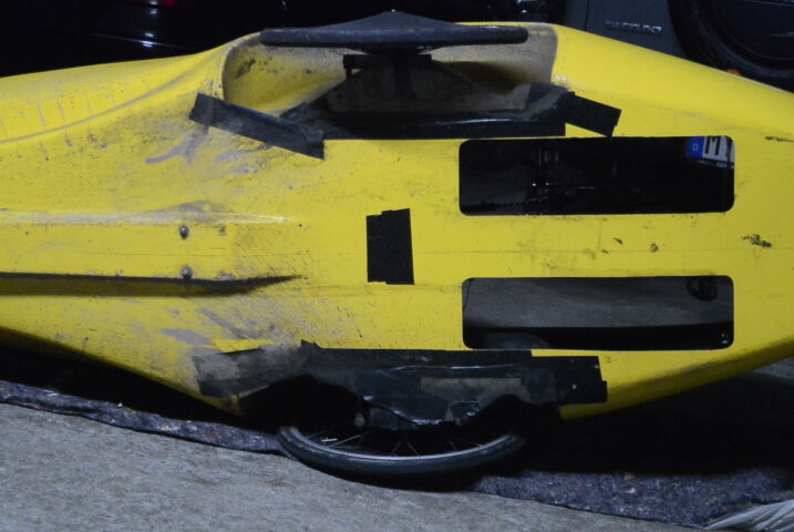
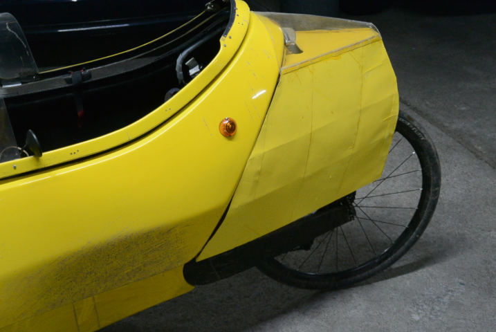
b) back closed successfully


The last bike is younger than mine and has an improved stiffness in the back. Such a tightly fitting back cover is impossible on my bike.

The 1st bike has originally been quite similar to mine (same year) except for


Please note the work Daniel Fenn has done to the wheel cases, the foot holes, the canopy (must have been closed originally), and the large hole in the top of the back plate.

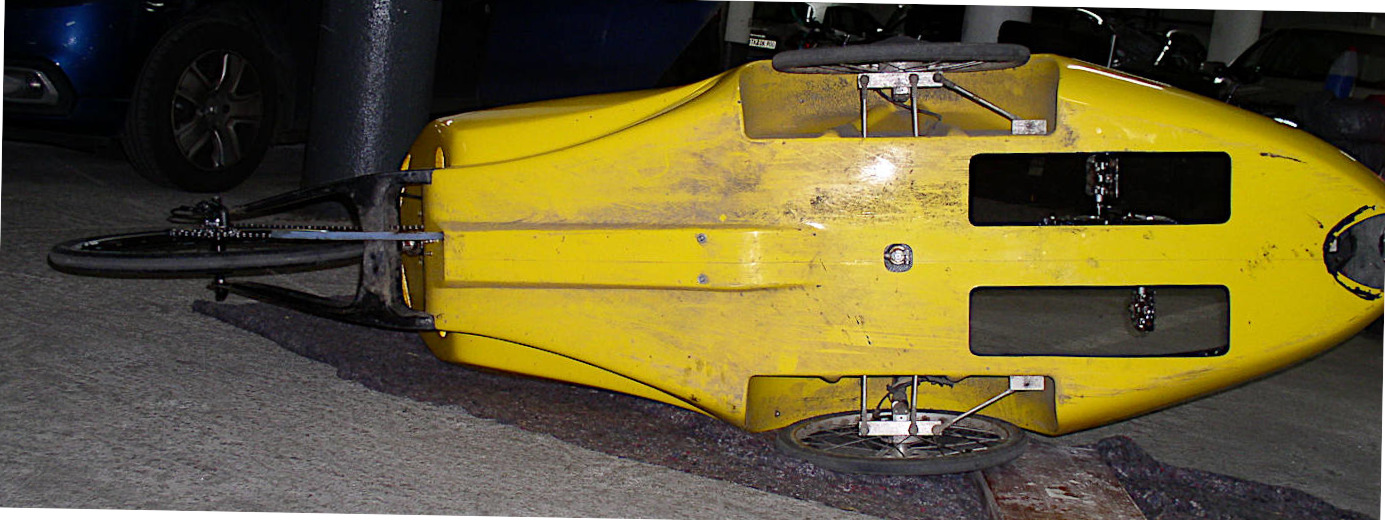
Similar holes can often be found in GoOnes with a closed canopy:


So far as an introduction.
Pleas note that i do not want to concentrate on just closing the back - this is obvious, and i will show You my 1st attempts later one, but to all the other issues and to possible alternatives to closing the back but leaving the design idea intact.


Last edited by beate; 01-29-2022 at 08:04 PM..
  Reply With Quote
Alt Today
Popular topics

Other popular topics in this forum...

   
Old 01-29-2022, 08:08 PM   #2 (permalink)
HPV Tussie
 
Join Date: Dec 2021
Location: Germany
Posts: 81
Thanks: 6
Thanked 63 Times in 36 Posts
Two old aerodynamic improvent have already been shown: the NACA-duct in the intake of the air box lead to a slight improvement (average 0.5-1 kph) and the extension of the wind screen shown in my 1st contribution leads to a similar speedup:


Just improving the angle of this addidional screen has a large effect - at some certain point where i never got beyond 33-34 kph i reached 38.5 kph which triggered the stationary speed camera at that point. Meanwhile the canopy has been further closed, but without any additional noticeable aerodynamic improvement.


Back the the aerodynamics of the tail:

the hole(s) in the top of the back plate should have aerodynamic effects, should'nt they?

Last edited by beate; 01-29-2022 at 08:20 PM..
  Reply With Quote
Old 01-30-2022, 05:57 AM   #3 (permalink)
HPV Tussie
 
Join Date: Dec 2021
Location: Germany
Posts: 81
Thanks: 6
Thanked 63 Times in 36 Posts
In the following pictures you can see the traces of splash water, predominantly caused by the weels on the wet road, but to some degree also showing the vortices of the air flow from the wheel boxes. What can we learn from them?


In comparison there seems to be a (small) real difference caused by the partial covering of the wheel boxes:

  Reply With Quote
Old 01-30-2022, 02:23 PM   #4 (permalink)
Master EcoModder
 
freebeard's Avatar
 
Join Date: Aug 2012
Location: northwest of normal
Posts: 27,752
Thanks: 7,796
Thanked 8,597 Times in 7,080 Posts
Quote:
What can we learn from them?
Not as much as tuft testing.

Those front wheel wells are as much an opportunity as the tail. They are upstream and will affect anything you do there.
__________________
.
.
Without freedom of speech we wouldn't know who all the idiots are. -- anonymous poster

____________________
.
.
Two wrongs don't make a right, but three lefts do.
  Reply With Quote
Old 01-30-2022, 03:27 PM   #5 (permalink)
HPV Tussie
 
Join Date: Dec 2021
Location: Germany
Posts: 81
Thanks: 6
Thanked 63 Times in 36 Posts
As well as what's happening at the end of the roof with its steep angle. Your right, i should continue working from front to back.

Apparently the roof does affect the behavior of the "strakes" you can see in one of the pics above (they mostly seem to affect the reaction to wind from the side).
  Reply With Quote
The Following User Says Thank You to beate For This Useful Post:
freebeard (01-30-2022)
Old 01-30-2022, 03:44 PM   #6 (permalink)
Master EcoModder
 
freebeard's Avatar
 
Join Date: Aug 2012
Location: northwest of normal
Posts: 27,752
Thanks: 7,796
Thanked 8,597 Times in 7,080 Posts
The front wheel wells remind me of the Saab 92 prototype [citation needed]. It had fully enclosed front wheels in a wide body, where yours are close-fitted like current BMW practice.

But underneath there is a gaping hole. Allowing for steer angles, a plate with a wavy outer edge would enclose maybe 50%.

Insofar as front skirts are concerned, I did a design in 2014 (that is frankly embarassing, and should be redone), that uses a Watts four-bar linkage to suspend the skirt. The significant feature is the top two bars are connected to prevent racking.
__________________
.
.
Without freedom of speech we wouldn't know who all the idiots are. -- anonymous poster

____________________
.
.
Two wrongs don't make a right, but three lefts do.
  Reply With Quote
Old 01-30-2022, 08:24 PM   #7 (permalink)
HPV Tussie
 
Join Date: Dec 2021
Location: Germany
Posts: 81
Thanks: 6
Thanked 63 Times in 36 Posts
Quote:
Originally Posted by freebeard View Post
Not as much as tuft testing.
A bit difficult when You're alone. Even more to view whats happening underneath the rolling vehicle. But anyway: i ordered a chep action camera and will indeed try to make some tuft testing. Camara mounted on a stick mounted to the rear wall.


Back to wheel box aerodynamics: You probably know pictures like that one - i'll show it to be able to refer to the terminology.


And let me refer to the pic of the bottom of my VM: You see that the back of the wheel box remains fairly clean, and most of the dirt is moved out by vortices B and E. Also note that E appears inward bound but aligns with the central chain tunnel and then leaves the bottom toward the back - but most of the dirt comes from Vortex R (as usual...).

Do You think that will mean tha a do not need to touch the back part of the wheel box, at least not in a first step?

What else can be seen:
the fairing allows for a lot of air entering the wheel box, mor or less on the complete lower half of the wheel. Right?

There are no clear signs of a vortex H - not too surprising regarding the geometry of the air intake (which btw prevented me from further closing the bottom of the wheelbox).

Closing the bottom of the wheel box has a clear impact on the flow within the box - there appears a separation between vortices B, S and E which is not present in the unmodified wheel box shown below, wehre the distribution of dirt is a lot more uniform, isnt'it?
  Reply With Quote
The Following User Says Thank You to beate For This Useful Post:
The Toecutter (02-15-2022)
Old 01-30-2022, 09:28 PM   #8 (permalink)
Master EcoModder
 
freebeard's Avatar
 
Join Date: Aug 2012
Location: northwest of normal
Posts: 27,752
Thanks: 7,796
Thanked 8,597 Times in 7,080 Posts
This is all above my pay grade.

That's a better wheelwell vortex diagram than the one I'd seen.

Looking again, it appears you do have the two underside pix and the first has baffles taped on. It's all dark.

Agreed it's difficult without a chase vehicle. I've though the best test track would be the 100ft circle. A camera at the center could capture data on all crosswind conditions.
__________________
.
.
Without freedom of speech we wouldn't know who all the idiots are. -- anonymous poster

____________________
.
.
Two wrongs don't make a right, but three lefts do.
  Reply With Quote
Old 01-31-2022, 10:46 AM   #9 (permalink)
Master EcoModder
 
aerohead's Avatar
 
Join Date: Jan 2008
Location: Sanger,Texas,U.S.A.
Posts: 15,909
Thanks: 23,994
Thanked 7,227 Times in 4,654 Posts
Cd 0.37

https://ecomodder.com/forum/member-a...vector-hpv.jpgAeronautical engineer Al Voight designed the fully-enclosed VECTOR in the early 1980s, if memory serves me.
VECTOR measured Cd 0.11.
That tail truncation is really costing you, although you'd need to run the numbers on a 'Lange-Heck' and see if you could live with the cost to do the modification.
Attached Thumbnails
Click image for larger version

Name:	member-aerohead-albums-other+vehicles+2-picture294-vector-hpv.jpg
Views:	38
Size:	33.9 KB
ID:	31647  
__________________
Photobucket album: http://s1271.photobucket.com/albums/jj622/aerohead2/

Last edited by aerohead; 01-31-2022 at 10:54 AM.. Reason: add photo link
  Reply With Quote
Old 02-01-2022, 07:12 PM   #10 (permalink)
HPV Tussie
 
Join Date: Dec 2021
Location: Germany
Posts: 81
Thanks: 6
Thanked 63 Times in 36 Posts
But a Cd of 0.11 is only "quite good" for velomobiles even at the time my GoOne had been built. Check for example the specs of the Milans: Milan Velomobil - Die Zukunft der Mobilität (Cw = Cd)

The latest successor of my vehicle also plays in that leage.

But anyway i think i should work from front to back in order to improve the situation. And i am looking for partial results: entirely closing the back is not possible due to the stability problem of my back wheel, which can only gradually improved, and it will destroy the design idea.

Anyway - there are some recent attempts:

a) successful


b) mostly unsuccessful

(i had closed the gaps with tape before driving)


Here an early version - i had to shorten the back because of the strong sideward moves of the wheel. The other GoOne is younger and had been improved by the manufacturer.

  Reply With Quote
The Following 4 Users Say Thank You to beate For This Useful Post:
aerohead (02-02-2022), BamZipPow (09-11-2022), freebeard (02-01-2022), The Toecutter (02-15-2022)
Reply  Post New Thread


Powered by vBulletin® Version 3.8.11
Copyright ©2000 - 2024, vBulletin Solutions Inc.
Content Relevant URLs by vBSEO 3.5.2
All content copyright EcoModder.com