02-28-2016, 10:50 AM
|
#2591 (permalink)
|
|
Ale Madeo
Join Date: Jan 2016
Location: Bariloche Patagonia Argentina
Posts: 32
Thanks: 22
Thanked 7 Times in 5 Posts
|
 power section
Hi everyone!
I start to build my power section of my controller.

The pcb is "hand-made", support 12 TO-3P IGBT, 6 electrolytic capacitors and the connectios of the bus bars and motor legs I made with copper bars.

I am anxious to finish and test.
with respect to the control board, I don't fabricate yet, but it is the design of Paul with some modification to components that get in my country and all SMD.
if I may a query, talking about power contactors of battery bank, I understand that we need two, one has preload resistance, but do not quite understand what´s the proper connection diagram.
I appreciate if anyone can give me a hand.
__________________
Los que dicen que es imposible, no deberían molestar a los que lo están intentando... 
|
|
|

|
|
The Following User Says Thank You to ale0502 For This Useful Post:
|
|
 Today Today
|
|
|
|
 Other popular topics in this forum...
|
|
|
|
|
02-28-2016, 12:05 PM
|
#2592 (permalink)
|
|
EcoModding Apprentice
Join Date: Oct 2009
Location: Jyvaskyla, Finland
Posts: 143
Thanks: 44
Thanked 35 Times in 28 Posts
|
Cool. Smaller power requirements there? I'd be up for similar power and control board. We have a moped to convert. ACIM of course. Hehe.
Connect precharge resistor in series with controller B+ and precharge contactor terminal to precharge capacitors. Battery+ --> precharge contactor --> precharge resistor --> controller B+. When capacitor voltage is high enough you can bypass the resistor. I used switching relay: when 12V was turned on precharge contactor went on. When precharge was done the relay switched precharge contactor off and main contactor on.
I can draw a simple image if you want to. There is also a simple precharging device available from zeva;
Zero Emission Vehicles Australia |
|
|
|
|
The Following User Says Thank You to mora For This Useful Post:
|
|
|
02-29-2016, 05:58 PM
|
#2593 (permalink)
|
|
Ale Madeo
Join Date: Jan 2016
Location: Bariloche Patagonia Argentina
Posts: 32
Thanks: 22
Thanked 7 Times in 5 Posts
|
Can you make a drawing please?
thank you very much
__________________
Los que dicen que es imposible, no deberían molestar a los que lo están intentando...
|
|
|
|
|
03-01-2016, 01:49 AM
|
#2594 (permalink)
|
|
EcoModding Apprentice
Join Date: Oct 2009
Location: Jyvaskyla, Finland
Posts: 143
Thanks: 44
Thanked 35 Times in 28 Posts
|
Here. Remember to set precharge delay correctly on your controller or you will weld contacts shut quickly. This is not a bulletproof solution and you should supervise voltage level during precharge.
Switching relay is not operated when key is turned on but it passes +12V to precharge relay. This should close precharge contactor. Whenever controller contactor output gives +12V to switching relay, precharge controller opens and main contactor closes. Ready to drive.
You can also substitute precharge contactor with Zeva product I linked earlier. Then you could use contactors on both battery terminals to isolate battery completely when it is not in use.
|
|
|
|
|
The Following 2 Users Say Thank You to mora For This Useful Post:
|
|
|
03-01-2016, 08:24 AM
|
#2595 (permalink)
|
|
PaulH
Join Date: Feb 2008
Location: Maricopa, AZ (sort of. Actually outside of town)
Posts: 3,832
Thanks: 1,362
Thanked 1,202 Times in 765 Posts
|
Awesome job, ale0502!! One way to improve the robustness of the precharge circuit is to pass the precharge wire through one of the 3 current sensors. You could wrap it around a few times to multiply the effect. If the current during precharge shows a surge, and then falls to zero, then it charged the capacitor bank. If the current sensor shows nonzero current continuously, then there's an IGBT that has failed shorted, or some other problem, and you should NOT close the main contactor.
I did the first test of the controller at high voltage. 376.5v peak. It wasn't stressful at all. I knew everything would be fine. haha. This was with the toyota MGR that e*clipse sent to me.
Last edited by MPaulHolmes; 03-01-2016 at 08:35 AM..
|
|
|
|
|
The Following 3 Users Say Thank You to MPaulHolmes For This Useful Post:
|
|
|
03-01-2016, 08:56 AM
|
#2596 (permalink)
|
|
PaulH
Join Date: Feb 2008
Location: Maricopa, AZ (sort of. Actually outside of town)
Posts: 3,832
Thanks: 1,362
Thanked 1,202 Times in 765 Posts
|
Here's one of the new boards I ordered:
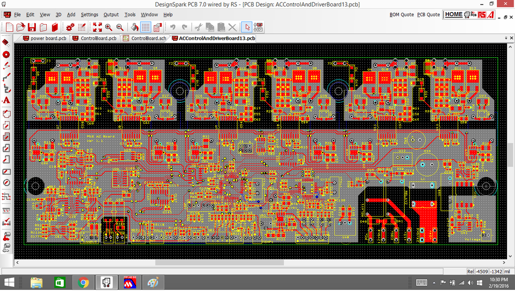
It's not here yet though. It does voltage monitoring, and has one of those resolver circuits right on board. You can also turn the resolver circuit off with the chip select pin on the resolver chip, so you can use the board to power something with a resolver, and then another motor that uses an encoder. The main thing about it is, it's all one sided surface mount, so that it can be put together faster.
I also ordered some boards that basically step the high voltage down to 0-3v or 4v, or whatever you want it to be. Then the main board isolates the 0-3v using a linear optocoupler, and makes a 0-3v output. That board also acts like a bleeder resistor for the bus cap(s), and also contains a 450vDC 10amp precharge relay (the same one Tesla uses!!). |
|
|
|
|
The Following 5 Users Say Thank You to MPaulHolmes For This Useful Post:
|
|
|
03-01-2016, 09:44 AM
|
#2597 (permalink)
|
|
Master EcoModder
Join Date: Sep 2010
Location: Saskatoon, canada
Posts: 1,488
Thanks: 746
Thanked 565 Times in 447 Posts
|
Quote:
Originally Posted by MPaulHolmes

It does voltage monitoring
|
That's the voltage of the pack, right?
Quote:
|
one of those resolver circuits right on board
|
Integration - woohoo!
Quote:
|
The main thing about it is, it's all one sided surface mount, so that it can be put together faster.
|
Or by people that are less co-ordinated 
Quote:
|
I also ordered some boards that basically step the high voltage down to 0-3v or 4v, or whatever you want it to be. Then the main board isolates the 0-3v using a linear optocoupler, and makes a 0-3v output. That board also acts like a bleeder resistor for the bus cap(s), and also contains a 450vDC 10amp precharge relay (the same one Tesla uses!!).
|
More integration! How do you tell when the pre-charge is done? To keep it flexible .. can you use .. maybe 80% .. of the pack voltage programmed in the config? |
|
|
|
|
The Following User Says Thank You to thingstodo For This Useful Post:
|
|
|
03-01-2016, 09:58 AM
|
#2598 (permalink)
|
|
Dreamer
Join Date: Nov 2013
Location: Australia
Posts: 350
Thanks: 95
Thanked 214 Times in 151 Posts
|
Integrating the precharge and monitoring the voltage is really excellent. It's one less thing to hookup and get right. Also means the controller can energise the main contactor with confidence that the precharge is done. Prevents that issue of the precharge circuit silently failing and the driver blissfully driving the car with the main contactor taking a beating each time the system is started.
Does the new board also contain the precharge resistor? If so what value? I imagine it would be fairly easy for the builder to add whatever value suited their set up.
|
|
|
|
|
The Following User Says Thank You to Astro For This Useful Post:
|
|
|
03-01-2016, 09:59 AM
|
#2599 (permalink)
|
|
PaulH
Join Date: Feb 2008
Location: Maricopa, AZ (sort of. Actually outside of town)
Posts: 3,832
Thanks: 1,362
Thanked 1,202 Times in 765 Posts
|
You can just watch the change in voltage over time. Or use 80% done, or anything you want! That part of the code doesn't exist yet, but would probably take like 30 minutes. A shorted IGBT would have a voltage drop of probably a few volts at the most, so the cap would never fill up. But if the pack voltage feedback is like > 12v (for example), and it isn't changing, then you would basically know it is good. A super paranoid person could also wrap the precharge wire through one of the current sensor windows. If current continues to flow, then the precharge failed.
The precharge resistor resides on the little precharge board. It has room for a 2Ohm to 1000Ohm Ohmite ceramic composition pulsEater (rated for like 5000v or something stupid like that. haha). Or you can just use a cheaper precharge resistor or 2 in parallel (there are 2 holes per resistor leg for the precharge resistor so you can use 2 little ones in parallel if you want). My thinking was, people poking their fingers around in the control section shouldn't have to deal with anything above 24v. That's why I first stepped down the high voltage to like 0-3v, and then run it to the control board.
Last edited by MPaulHolmes; 03-01-2016 at 10:04 AM..
|
|
|
|
|
The Following 3 Users Say Thank You to MPaulHolmes For This Useful Post:
|
|
|
03-01-2016, 03:53 PM
|
#2600 (permalink)
|
|
Master EcoModder
Join Date: Sep 2009
Location: Ireland
Posts: 734
Thanks: 26
Thanked 304 Times in 171 Posts
|
Need boards........must build.........
__________________
Now, Cole, when you shift the gear and that little needle on the ammeter goes into the red and reads 2000 Amps, that's bad.
www.evbmw.com
|
|
|
|
|