02-15-2012, 11:06 PM
|
#251 (permalink)
|
|
Master EcoModder
Join Date: May 2008
Location: Maynard, MA Eaarth
Posts: 7,908
Thanks: 3,475
Thanked 2,953 Times in 1,846 Posts
|
I probably have, but I'm not remembering the details.
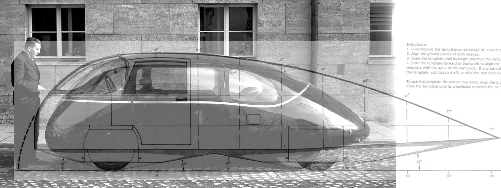
Here's a profile comparison with the ideal template:
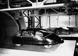
And here's the wind tunnel image:
Here's a brief video in green light that may be the image you are referring to?
http://www.magnus.de/video/der-schlo...nal-83785.html
|
|
|

|
|
The Following User Says Thank You to NeilBlanchard For This Useful Post:
|
|
 Today Today
|
|
|
|
 Other popular topics in this forum...
|
|
|
|
|
02-16-2012, 05:57 PM
|
#252 (permalink)
|
|
Master EcoModder
Join Date: Jan 2008
Location: Sanger,Texas,U.S.A.
Posts: 16,548
Thanks: 24,522
Thanked 7,441 Times in 4,821 Posts
|
windkanal
Neil,that's the image.The smoke flow off the back of the car suggests that the air would prefer to follow a less steeply sloped roofline.
Your photo gallery is great.Thanks again!
|
|
|
|
|
02-17-2012, 09:18 AM
|
#253 (permalink)
|
|
Recreation Engineer
Join Date: Dec 2009
Location: Somewhere USA
Posts: 525
Thanks: 333
Thanked 138 Times in 103 Posts
|
Quote:
Originally Posted by ERTW

Kamperbob, you are correct. I wanted to investigate the prismatic shape because firstly I don't see anybody using the revolved shape. The template works for a revolved shape, or even a high aspect ratio wing. However, cars are narrow boxes. Flow around such a body is very different. That's why I'm modeling a prism. Perhaps Aerohead can comment.
You could argue that the box fish is the slipperiest shape found in nature. Boxes are also much more pragmatic than footballs; they offer more usable space and are easier to build than compound curves.
Aerohead, I put the template up against a 2010 GMC Sierra, and found that it only goes out to 45%. What is the minimum Cd at that point?
My template approximation is good to about 60%. The zebra stripes should be concentric circles - as they are at the peak. You can see the broad space and the reverse stripe on the tail which confirms a discontinuity.
|
Quote:
Originally Posted by ERTW
Aerohead, I used an equation based spline for the back. It makes it really easy to shape the curve as I like.
As a confirmation of the hard work you've put in, the revolved solid shows smooth contours all the way out to the tail. So the boxed shape requires a different approach as I'd hypothesized. I hope to have some CFD analysis done this weekend.
|
ETRW, I hear you. And I'm delighted to see your revolved model drawn up in solid works. Everyone I know who does simulation professionally validates the model first. If CFD on a highly developed template form confirms attachment that's good. If a slightly stubbier/steeper version (ie, violates template rules) shows separation that's better. Because then you can play with other geometries (ie, prismatic) with higher confidence in computed results. Of course wind tunnel, tufts and/or field tested MPG would wrap it all up with a bow on top. Filling an analysis hole is still an excellent contribution to our collective body of knowledge.  |
|
|
|
|
02-17-2012, 09:35 AM
|
#254 (permalink)
|
|
Recreation Engineer
Join Date: Dec 2009
Location: Somewhere USA
Posts: 525
Thanks: 333
Thanked 138 Times in 103 Posts
|
Quote:
Originally Posted by aerohead
To fully exploit the 'Template' with a pickup would require that the truck box roll into tumblehome as it progresses rearward,allowing the elliptical cross-section to evolve.
I was in the process of doing this to the Dodge pickup when the T-100 showed up in my driveway.So this project has languished since 2005.KamperBob is the only person who has seen it.
|
What an honor. Phil, your Dodge project deserves some limelight too. I look forward to that day. Meanwhile, I'm attaching some good luck for your T100 projects.
My focus this winter has been leisure travel. Yet some mornings I awoke to find my subconscious mind was in design mode overnight, dreaming up the ultimate camper. Who knows I may get the bug and build it yet. We'll have to see how other priorities shape up as the next year plays out. Having my own shop again would be key to that of course. If I'm on the road instead, then I'd be more than happy to lend a hand to Phil, Brett or somebody else to help move their projects along. It's all good. |
|
|
|
|
The Following User Says Thank You to KamperBob For This Useful Post:
|
|
|
02-17-2012, 09:42 AM
|
#255 (permalink)
|
|
Master EcoModder
Join Date: Apr 2011
Location: Tacoma WA
Posts: 1,404
Thanks: 746
Thanked 532 Times in 348 Posts
|
I found this site a wee bit too late, or my bed boxes would look totally different, with that tumblehome that Phil describes. Ah well. Bob, I have had many a sleepless morning, working on the details of my trailer. I have other projects I must finish first, but the mind, it is a terrible thing. It wanders ahead so far!
__________________

2007 Dodge Ram 3500 SRW 4x4 with 6MT
2003 TDI Beetle
2002 TDI Beetle
currently parked - 1996 Dodge 2500 Cummins Turbodiesel
Custom cab, auto, 3.55 gears
|
|
|
|
|
02-18-2012, 11:56 PM
|
#256 (permalink)
|
|
EcoModding Apprentice
Join Date: Jan 2012
Location: Toronto
Posts: 130
Bu - '08 Chevrolet Malibu LS 90 day: 32.29 mpg (US)
Thanks: 52
Thanked 73 Times in 36 Posts
|
Quote:
Originally Posted by KamperBob
ETRW, I hear you. And I'm delighted to see your revolved model drawn up in solid works. Everyone I know who does simulation professionally validates the model first. If CFD on a highly developed template form confirms attachment that's good. If a slightly stubbier/steeper version (ie, violates template rules) shows separation that's better. Because then you can play with other geometries (ie, prismatic) with higher confidence in computed results. Of course wind tunnel, tufts and/or field tested MPG would wrap it all up with a bow on top. Filling an analysis hole is still an excellent contribution to our collective body of knowledge. |
By the same logic I may as well CFD a sphere at various Re. I really can't explore every permutation with my old a$$ pc. I took the template for a test drive today...9 hours later it's still thinking. You may not hear from me for a while...
Some preliminary work suggests the template's nose should be pointy like Morelli, and not blunt. |
|
|
|
|
02-20-2012, 12:48 AM
|
#257 (permalink)
|
|
EcoModding Apprentice
Join Date: Jan 2012
Location: Toronto
Posts: 130
Bu - '08 Chevrolet Malibu LS 90 day: 32.29 mpg (US)
Thanks: 52
Thanked 73 Times in 36 Posts
|
so...21 hours later...I realized how to drastically cut calculation time. 
Results for a sharp nosed revolved template - 295 N total drag => Cd = 0.178
The frontal area is 3.0656 m^2 (60" tall, 5" ground clearance)
air speed is 30 m/s (108 kph or 67 mph)
air density at 20°C is 1.204 kg/m^3
I realised that from 70% to 80% of the template is a straight section, whereas I use a curve. Phil, if you were expecting a lower Cd, I strayed from the template, as you can see, and this is what I got. This software has good correlation. I didn't want to go beyond solid models and get into surfaces, so I'll leave it at that.
It's expected, and still pleasant confirmation, to see the surface pressure *increases* near the very tip of the tail. I made the nose sharper because there was a large high pressure area on the blunt nose.
Tomorrow will be an interesting day at the University of Toronto  |
|
|
|
|
The Following 10 Users Say Thank You to ERTW For This Useful Post:
|
|
|
02-20-2012, 04:56 PM
|
#258 (permalink)
|
|
Aero Deshi
Join Date: Jan 2010
Location: Vero Beach, FL
Posts: 1,065
Thanks: 430
Thanked 669 Times in 358 Posts
|
All I have to say about this is HA! It illustrates what I've been saying all along that if the pressure on the front is the same as that on the back, then the air sliding down the backside is returning the energy to the car that it took to move it out of the way, this to me is the fundamental basis for aero design.
|
|
|
|
|
02-20-2012, 06:59 PM
|
#259 (permalink)
|
|
Master EcoModder
Join Date: Jan 2008
Location: Sanger,Texas,U.S.A.
Posts: 16,548
Thanks: 24,522
Thanked 7,441 Times in 4,821 Posts
|
quanta
Quote:
Originally Posted by ERTW
so...21 hours later...I realized how to drastically cut calculation time.
Results for a sharp nosed revolved template - 295 N total drag => Cd = 0.178
The frontal area is 3.0656 m^2 (60" tall, 5" ground clearance)
air speed is 30 m/s (108 kph or 67 mph)
air density at 20°C is 1.204 kg/m^3
I realised that from 70% to 80% of the template is a straight section, whereas I use a curve. Phil, if you were expecting a lower Cd, I strayed from the template, as you can see, and this is what I got. This software has good correlation. I didn't want to go beyond solid models and get into surfaces, so I'll leave it at that.
It's expected, and still pleasant confirmation, to see the surface pressure *increases* near the very tip of the tail. I made the nose sharper because there was a large high pressure area on the blunt nose.
Tomorrow will be an interesting day at the University of Toronto |
The template is modeled from the aft-body of a 2.5:1 streamline body of revolution.
In free flight is has a coefficient of aerodynamic drag of Cd 0.04
In ground proximity Cd 0.08.
At 70% Cd 0.09
At 80% Cd 0.083
I allowed Cd 0.13 with wheels @ 100%
Maybe Cd 0.12 or less with wheel fairings.
I made the nose more blunt,as all my fluid mechanics text regarded a convex hemispherical nose to be plenty good below transonic flow ( about 250 mph for automobiles).
All of Hucho's tables for crosswind drag coefficients show the bulbous nose to have the lowest Cd.
If the nose is pushed out any at all,the opportunity for separation is increased,as now, the corner radius is reduced,and with it, stability of the turbulent boundary layer which cannot feed energy around the sharper corner.
Hucho's emphasis for drag reduction is in aft-body streamlining,hence the tail. |
|
|
|
|
02-21-2012, 09:45 AM
|
#260 (permalink)
|
|
Recreation Engineer
Join Date: Dec 2009
Location: Somewhere USA
Posts: 525
Thanks: 333
Thanked 138 Times in 103 Posts
|
Quote:
Originally Posted by ERTW
so...21 hours later...I realized how to drastically cut calculation time.
Results for a sharp nosed revolved template - 295 N total drag => Cd = 0.178
The frontal area is 3.0656 m^2 (60" tall, 5" ground clearance)
air speed is 30 m/s (108 kph or 67 mph)
air density at 20°C is 1.204 kg/m^3
I realised that from 70% to 80% of the template is a straight section, whereas I use a curve. Phil, if you were expecting a lower Cd, I strayed from the template, as you can see, and this is what I got. This software has good correlation. I didn't want to go beyond solid models and get into surfaces, so I'll leave it at that.
It's expected, and still pleasant confirmation, to see the surface pressure *increases* near the very tip of the tail. I made the nose sharper because there was a large high pressure area on the blunt nose.
Tomorrow will be an interesting day at the University of Toronto |

Thanks, dude! Now I'm really looking forward to how this compares with your prismatic template model.
Your earlier point, ERTW, about modeling spheres as known problem solutions is actually a great idea! 
So what was the trick for cutting computation time?
Last edited by KamperBob; 02-21-2012 at 09:46 AM..
Reason: typo
|
|
|
|
|