 02-15-2015, 06:35 PM
|
#1701 (permalink)
|
|
Permanent Apprentice
Join Date: Jul 2010
Location: norcal oosae
Posts: 523
Thanks: 351
Thanked 318 Times in 215 Posts
|
Thank you, Piotrsko!  I always welcome rocket-science! 
In general, I am concerned about the data line recieving the noise. I figured the motor controller would be THE location of maximum noise. Those poor signal wires would be within inches of the IGBT's that are switching 650V, 150A @ 20kHz. 
The differential pair wires are ( sorry - sorta OT ) on the BMS, communicating the info from the data gathering IC's to the central computer. Data is transmitted at about 1Gb/s, and unfortunately I have no control of the speed, just the amplitude.
**EDIT** this is exactly like CAN on the physical level! So, I guess it's ON topic, 'cause I would like to communicate things to/from the motor controller using CAN and Paul has already supplied CAN port hardware.  CAN bus - Wikipedia, the free encyclopedia
In my case, I'm trying to reduce the number of wires and connections. This is why I was so happy to find that intermittent twisted-pair cable. I am dealing with a system where the cable length could approach 10 feet, and the voltage between the low side and high side could approach 650V.
The reason I was confused about the value of a shield is that the design advice for a PCB indicated a ground or power plane was actually not advantageous in a stripline application ( buried signal traces in a 4 layer board ) HOWEVER - don't quote this - I may merely be confused. 
I've found twisted pair/shielded wires, but often they were very expensive and I never found a good way to terminated them. (common is Ethernet)
- E*clipse
|
|
|

|
 Today Today
|
|
|
|
 Other popular topics in this forum...
|
|
|
|
|
02-15-2015, 06:53 PM
|
#1702 (permalink)
|
|
Master EcoModder
Join Date: Sep 2010
Location: Saskatoon, canada
Posts: 1,488
Thanks: 746
Thanked 565 Times in 447 Posts
|
Quote:
Originally Posted by Piotrsko

pretty much if you want to stop receipt of EMR, then sheilding on the pairs, then the bundle sheilded with a foil or a braid and tied to different GROUNDS (not negative battery) at one end only.
Not an instrumentation super, but instrumentation Tech at Edwards AFB rocket site thruster test lab.
|
What I'm told pretty much matches what you listed. individual shields, plus an overall shield.
I have to ask about the different grounds, though. With an isolated switching power supply .. which shields are connected to which grounds? And if the PS negative is not one of them .. how do you 'make' a signal ground?
Our instrument supervisor came up through the ranks, so he's the most experienced tech I know. He has explained grounds to me many times .. Obviously I'm a slow learner. I just don't seem to be able to keep it straight. |
|
|
|
|
The Following User Says Thank You to thingstodo For This Useful Post:
|
|
|
02-15-2015, 07:06 PM
|
#1703 (permalink)
|
|
Master EcoModder
Join Date: Sep 2010
Location: Saskatoon, canada
Posts: 1,488
Thanks: 746
Thanked 565 Times in 447 Posts
|
Quote:
Originally Posted by e*clipse
In general, I am concerned about the data line recieving the noise. I figured the motor controller would be THE location of maximum noise. Those poor signal wires would be within inches of the IGBT's that are switching 650V, 150A @ 20kHz.
The differential pair wires are ( sorry - sorta OT ) on the BMS, communicating the info from the data gathering IC's to the central computer. Data is transmitted at about 1Gb/s, and unfortunately I have no control of the speed, just the amplitude.
**EDIT** this is exactly like CAN on the physical level! So, I guess it's ON topic, 'cause I would like to communicate things to/from the motor controller using CAN and Paul has already supplied CAN port hardware.
CAN bus - Wikipedia, the free encyclopedia
In my case, I'm trying to reduce the number of wires and connections. This is why I was so happy to find that intermittent twisted-pair cable. I am dealing with a system where the cable length could approach 10 feet, and the voltage between the low side and high side could approach 650V. |
We run Devicenet (a variant of CANbus) in electrical rooms, run in the same cable tray with 575VAC, within a couple of feet of 4160VAC. It is *VERY* robust. But the data rate is comparatively low. There is a conductor described as ground, but the cables have no overall shielding, and no shielding on the differential pair. There is a terminating resistor at each 'end' of the bus .. but that's it.
The way that Devicenet powers communication is .. interesting ..
A separate 24VDC power supply, that is rated for the Devicenet spec, is used to supply the power for the isolated side of each communication board, in each device on the network. That's ALL that is powered up by that power supply. It disables on short circuit, ground fault, and a host of other problems but by doing that it protects the communication boards for each device.
Would that method give you good isolation between the DC bus and the communications? I'm not sure if that is paranoid enough for the communications between controllers in a car. But it's something that is used in industry and I thought it might apply. |
|
|
|
|
The Following User Says Thank You to thingstodo For This Useful Post:
|
|
|
02-15-2015, 09:04 PM
|
#1704 (permalink)
|
|
Permanent Apprentice
Join Date: Jul 2010
Location: norcal oosae
Posts: 523
Thanks: 351
Thanked 318 Times in 215 Posts
|
VERY interesting! Thank you, thingstodo.
This is exactly what I was looking for - a robust industrial solution that might extend to automotive use. It's good to hear the system works around the 575VAC, because this data line may have to connect to battery cells in the front and back. This means the data line will be in a "tray" going from the rear of the car to the front along with the main DC power bus (and all the noise that gets injected onto the power bus from the motor controllers.)
The BMS system I'm working on is actually pretty similar in some ways. It's called isoSPI, and works at 1Mbps. (Sorry, I was wrong about the 1Gbps statement earlier  )
LTC6804-1/LTC6804-2 - Multicell Battery Monitors - Linear Technology
Anyway, it uses a driver IC that translates standard SPI to a differential pair isoSPI. The system can be configured as either a daisy chain set-up or a parallel setup with multiple nodes on one bus. The voltage is much lower than 24V, but it does use termination resistors and each node is isolated from the bus with a transformer like a 1:1 ethernet transformer.
IF I understand the shielding correctly (and PLEASE correct me if I'm wrong) the shield provides a path for the noise to go to "ground." In my case, I may be able to use short (about 10" long) shields connecting to each battery module's low side "ground" This would limit the voltage potential between the data wires and the shield to about 50V. Or would this not work because that low side "ground" could be at 600V, perhaps higher than the noise source?
I would like the communication bus - whether this one or the CAN bus to the motor controller to be extremely - read - "automotive" robust. However, I do NOT plan on putting any control critical information such as ABS or throttle position on the bus. I do think it would be really cool to put information such as motor temp, motor controller temp, etc. on the CAN bus using standard automotive CAN protocol. 
- E*clipse
Quote:
Originally Posted by thingstodo
We run Devicenet (a variant of CANbus) in electrical rooms, run in the same cable tray with 575VAC, within a couple of feet of 4160VAC. It is *VERY* robust. But the data rate is comparatively low. There is a conductor described as ground, but the cables have no overall shielding, and no shielding on the differential pair. There is a terminating resistor at each 'end' of the bus .. but that's it.
The way that Devicenet powers communication is .. interesting ..
A separate 24VDC power supply, that is rated for the Devicenet spec, is used to supply the power for the isolated side of each communication board, in each device on the network. That's ALL that is powered up by that power supply. It disables on short circuit, ground fault, and a host of other problems but by doing that it protects the communication boards for each device.
Would that method give you good isolation between the DC bus and the communications? I'm not sure if that is paranoid enough for the communications between controllers in a car. But it's something that is used in industry and I thought it might apply.
|
|
|
|
|
|
02-16-2015, 12:40 AM
|
#1705 (permalink)
|
|
Master EcoModder
Join Date: Sep 2010
Location: Saskatoon, canada
Posts: 1,488
Thanks: 746
Thanked 565 Times in 447 Posts
|
Quote:
Originally Posted by MPaulHolmes
The DC-DC has 2 spots (maybe 3 if you count a screw spot) where you can screw in M3 screws (no nut required). But that would require a couple extra holes in the enclosure. Now that I know the screw came out in shipping, I think it would be a good idea to use those extra 2 screw holes (and the 3rd hole too if you want). You don't need a full 50w DC-DC. It's just that the 15 or 20w versions were out of stock. Those are smaller and lighter. Oh well.
|
Just to make sure we are on the same page .. sometimes it's hard to tell
One terminal, 12V + in, came loose in shipping. The screws that fix the DC/DC to the case were in just a bit loose, but they held the DC/DC in place.
See photo |
|
|
|
|
The Following User Says Thank You to thingstodo For This Useful Post:
|
|
|
02-16-2015, 12:57 AM
|
#1706 (permalink)
|
|
PaulH
Join Date: Feb 2008
Location: Maricopa, AZ (sort of. Actually outside of town)
Posts: 3,832
Thanks: 1,362
Thanked 1,202 Times in 765 Posts
|
Oh! I had meant the 2 screw holes on the bottom for attaching the base to a surface (3 if you count the hole that contains a M3 nut too). Thanks for clarifying!
I finished the code for PI loop tuning. It compiles and should work without much fuss. Now I need to include the test for finding the ideal rotor time constant. We're on a roll, so I'll modify the AC controller code again, and add a serial command for this too. I never thought it would be practical all in one hex file, but it's proving to be a lot easier than I thought it would be.
|
|
|
|
|
The Following 2 Users Say Thank You to MPaulHolmes For This Useful Post:
|
|
|
02-16-2015, 12:58 AM
|
#1707 (permalink)
|
|
Master EcoModder
Join Date: Sep 2010
Location: Saskatoon, canada
Posts: 1,488
Thanks: 746
Thanked 565 Times in 447 Posts
|
Quote:
Originally Posted by thingstodo
I've been busy with other things - should be able to power it up on Sunday, but first I need to:
- get the contactors connected
- get a 48V battery pack and precharge resistor connected
- get my test 5 HP motor connected
- make a bushing to fit my encoder to the motor shaft
- get it all connected up
|
Most of it is in the basement now. Pictures are:
- Contactors, precharge resistor, 80 amp 125VDC breaker, on the high voltage side of the controller
- 5 HP 3 phase 208V motor, encoder without adapter/bushing to mount encoder on the motor shaft (:
- motor leads sitting inside U, V, and W from the controller
- 48V gel cell battery pack .. that *MAY* supply 20 amps for a few seconds
- low voltage side of the controller with connectors
Still to bring in - 12V lithium battery, throttle, slide switch to enable controller
Still to read - where to connect the throttle, where to connect the 'ignition' switch
Still to fab - encoder mount for motor shaft |
|
|
|
|
The Following User Says Thank You to thingstodo For This Useful Post:
|
|
|
02-16-2015, 01:17 AM
|
#1708 (permalink)
|
|
PaulH
Join Date: Feb 2008
Location: Maricopa, AZ (sort of. Actually outside of town)
Posts: 3,832
Thanks: 1,362
Thanked 1,202 Times in 765 Posts
|
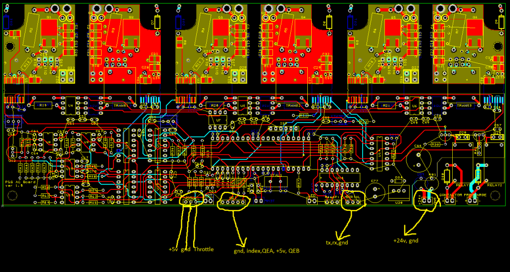
Holy mackeroni, I forgot about the encoder ticks. That needs to be programmable! I'll include that next with the rotor time constant addition. Then I'll send you a big fat .hex file and .c and .h files that have it all. Here's a pinout for the control board. (You don't need the index pin for the encoder. the microcontroller will just ignore it in the case of an ac induction motor):
 |
|
|
|
|
The Following 2 Users Say Thank You to MPaulHolmes For This Useful Post:
|
|
|
02-16-2015, 11:24 AM
|
#1709 (permalink)
|
|
Somewhat crazed
Join Date: Sep 2013
Location: 1826 miles WSW of Normal
Posts: 4,574
Thanks: 597
Thanked 1,256 Times in 1,108 Posts
|
BAH, 10 ft. No biggie. 10 MV signal 1000 ft in a mega watt EMR environment, thats exciting. worse case, get a roll of aluminum foil and wrap the wires in it, or metal duct tape foil. Think FARADAY cage.
I believe you are overthinking this.
Back to our regularily sponsored discussion. Sorry for the hi-jack
|
|
|
|
|
The Following User Says Thank You to Piotrsko For This Useful Post:
|
|
|
02-16-2015, 01:00 PM
|
#1710 (permalink)
|
|
Master EcoModder
Join Date: Sep 2010
Location: Saskatoon, canada
Posts: 1,488
Thanks: 746
Thanked 565 Times in 447 Posts
|
Quote:
Originally Posted by Piotrsko
BAH, 10 ft. No biggie. 10 MV signal 1000 ft in a mega watt EMR environment, thats exciting. worse case, get a roll of aluminum foil and wrap the wires in it, or metal duct tape foil. Think FARADAY cage.
I believe you are overthinking this.
Back to our regularily sponsored discussion. Sorry for the hi-jack
|
The output of the AC drive is a pulse train. I think Paul is starting out at 8 Khz, although that may change. 0VDC to maybe 600VDC, or 850 VDC (if I use a 575VAC motor). Analyzing harmonics appears to me to be more of a black art than science. What appear to be very small changes can create resonance at some higher frequency (100s of Khz or Mhz) and mess with all sorts of electronics.
The guys at EVTV have identified problems with commercially available AC controllers, where the AC fed to the motor is interfering with signals into and out of the controller - like the throttle, the regen signal from the brakes, even the low voltage DC that powers the controller. EVTV builds have mysteriously blown up many DC/DC converters and no one appears to know why. EVTV sells shielded single-conductor power cables to mitigate the noise. And they have shielded low voltage cable as well, although they don't appear to emphasize using it. There are other video shows and other suppliers that have had problems, but EVTV appears to publish these sorts of problems.
Some people are having issues, in their cars, with the hardware they have built or purchased. And I'm a paranoid. In my opinion, it's better to talk about what is over-the-top and what is practical and will be good-enough .. than to agonize over a system that has intermittent problems that you can't track down.
Getting towed home is not the way I want people to remember my electric car.
|
|
|
|
|
The Following 2 Users Say Thank You to thingstodo For This Useful Post:
|
|
|


