09-12-2013, 02:13 PM
|
#91 (permalink)
|
|
Batman Junior
Join Date: Nov 2007
Location: 1000 Islands, Ontario, Canada
Posts: 22,518
Thanks: 4,071
Thanked 6,961 Times in 3,605 Posts
|
He's not. He's a signature spammer who was just banned.
|
|
|

|
 Today Today
|
|
|
|
 Other popular topics in this forum...
|
|
|
|
|
09-12-2013, 06:40 PM
|
#92 (permalink)
|
|
Master EcoModder
Join Date: Jan 2008
Location: Sanger,Texas,U.S.A.
Posts: 15,908
Thanks: 23,993
Thanked 7,226 Times in 4,653 Posts
|
images
Quote:
Originally Posted by kach22i

|
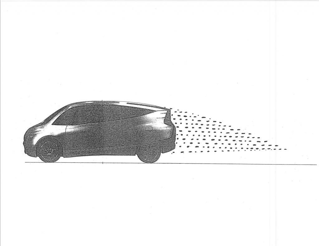
I wanted to mention that the upper set of images are 2-D flow studies and lack the longitudinal vortices which are depicted in the bottom 3-D flow study representation
The center table is from Buchheim's measurements of the Schl'o'r car,circa 1938, put together by Prandtl,Rumpler,and Schl'o'r,and I think it's A.V.A. G'o'ttingen,not D.L.R..
__________________
Photobucket album: http://s1271.photobucket.com/albums/jj622/aerohead2/
|
|
|
|
|
09-21-2013, 07:59 PM
|
#93 (permalink)
|
|
Master EcoModder
Join Date: Feb 2012
Location: Australia
Posts: 355
Thanks: 5
Thanked 76 Times in 50 Posts
|
The template or something very close to it is the best guide to reducing aerodynamic drag, this has been shown to be the case both in nature through years of evolution for both air and water and also in man made designs.
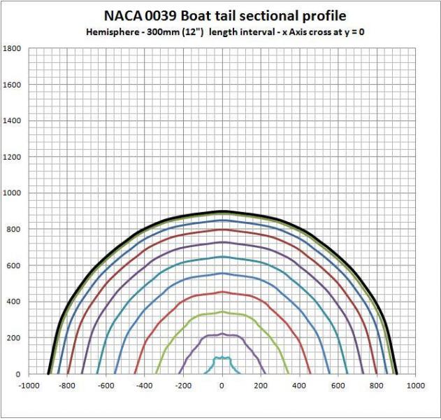
The two images I posted before are what triggered my understanding when I was playing with the NACA 0039 air foil equation:
The hemisphere shows perfectly what the template is based on a 3d transition from all sides, but the square shows something completely different using the same equation, and this is the part that most people are missing I think when using scaling.
The question is what is the ground reference in the scaling, or more appropriately what is the focal point of the design?
For the pure template as a 3d full form object in free air it is the centre line from tip to tail, as a half body in close ground proximity it is the centreline on the ground. With the square as shown when the template type equation is applied to all points, the corners lag because they have the greatest distance from the focal point, hence the longest tail profile, whereas the sides close to the ground are nearest to the focal point, hence shortest tail profile and come in quickest forming the odd shape at the rear.
If you raise vehicle off the ground somewhat then there is a question as to whether the centreline on base of the vehicle then becomes the focal point and this would produce a shape somewhat like the Pinnafarina "Banana car".
As for apendages and attachments, out hanging free mirrors are basically seperate objects and can be scaled according to their size, scoups, shrouds, mudguards etc attached to flatish surfaces on vehicle can be scaled as if the vehicle panel is ground and this is their focal point.
As for a full boattail on a conventional vehicle, the template provides a guide for the profile, the sides theoretically could come in much quicker, but only if the corners are apropriately scaled as well, and they would present the longest tail.
This I think is the cause of the counter rotational vorticies, not the sudden meeting of top and side air, but simply the fact that the corner lines are curved in too quickly and there is not enough time for that air to decelerate in an orderly fashion.
Using the profile taper for the sides as well as top and gentle rounding can minimise this as there is an excess of air on the sides then and some of this can flow over and fill the void being left on the corners.
One of the ideas I have been thinking about is whether this problem can be solved by using a volume calculation using crossectional area and applying the % change in angle as set out by the template to the change in crosssectional area, so effectively merging the squareback at rear of vehicle to eliptical at end of boattail.
Last edited by Tesla; 09-21-2013 at 09:43 PM..
|
|
|
|
|
09-21-2013, 09:22 PM
|
#94 (permalink)
|
|
Not Doug
Join Date: Jun 2012
Location: Show Low, AZ
Posts: 12,186
Thanks: 7,225
Thanked 2,217 Times in 1,708 Posts
|
Will you please explain from which direction I would be looking at the Template to see this representation? The first image looks like the front, from the front, or from above, if it is a quarter sphere, it would look the same, but the second image confuses me!
|
|
|
|
|
09-21-2013, 10:45 PM
|
#95 (permalink)
|
|
Master EcoModder
Join Date: Feb 2012
Location: Australia
Posts: 355
Thanks: 5
Thanked 76 Times in 50 Posts
|
Basically looking from the tail back to the widest section, kind of like the rib cage of the beast, cross sections down the length of the tail at 300mm intervals.
I put these together while I was looking at how to construct a trailer canopy, the idea being that I can print out the co ordinates of each section, transfer to cardboard, cut out and then line up sections to create a formwork to put the skin on.
Not exactly the same as template, but very close and as we don't know how accurate the details of the template are originally, no offense to Phil, but I also graphed rates of change in the template angles and found that it is a twin hump curve and I imagine good airflow would want consistant change and not be accelerated and then decelerated multiple times. This inconsistancy I believe comes from incorporating a number of rules, but the numbers and angles have been rounded hence the template as we know it does not have a specific equation, but I've found a couple that come very close.
|
|
|
|
|
The Following User Says Thank You to Tesla For This Useful Post:
|
|
|
07-01-2014, 10:13 PM
|
#96 (permalink)
|
|
Drive less save more
Join Date: Jul 2011
Location: Vancouver Island, Canada
Posts: 1,189
Thanks: 134
Thanked 162 Times in 135 Posts
|


[ [/url]


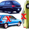
In the top left the steeper slope leaves the smallest wake , with the below depiction showing a diagram with a fairly steeply sloped back on it.
Which makes me think the Boxfish *may* be made less steep to accommodate the passenger seating more then being a perfect angle, it may be a compromise, as with the audi A2 slope, I am thinking.
Could be the steeper angle is actually better ? here is a good example of what I am referring to as "perhaps" the better slope.
The SolarWind looks very close to my Beetles shape, I wonder if it's profile is the more efficient one ..?
on a side note:
I just ordered a anemometer gauge better know as a wind meter , for small scale wind tunnel test so I can test with accurate wind speeds.
__________________
Save gas
Ride a Mtn bike for errands exercise entertainment and outright fun
__________________

|
|
|
|
|
07-02-2014, 12:19 PM
|
#97 (permalink)
|
|
Master EcoModder
Join Date: Jul 2011
Location: Ann Arbor, Michigan
Posts: 4,158
Thanks: 120
Thanked 2,790 Times in 1,959 Posts
|
Quote:
Originally Posted by ecomodded
In the top left the steeper slope leaves the smallest wake , with the below depiction showing a diagram with a fairly steeply sloped back on it.
|
There is more ink in that little swirl, making me believe it is more ferocious and turbulent despite it's diminutive size.
This concentrated energy may be more drag inducing despite graphic representation.
Just a guess on my part.
Others hopefully will chime in. |
|
|
|
|
07-02-2014, 06:04 PM
|
#98 (permalink)
|
|
Master EcoModder
Join Date: Jan 2008
Location: Sanger,Texas,U.S.A.
Posts: 15,908
Thanks: 23,993
Thanked 7,226 Times in 4,653 Posts
|
slope
Quote:
Originally Posted by ecomodded
[ [/url]
In the top left the steeper slope leaves the smallest wake , with the below depiction showing a diagram with a fairly steeply sloped back on it.
Which makes me think the Boxfish *may* be made less steep to accommodate the passenger seating more then being a perfect angle, it may be a compromise, as with the audi A2 slope, I am thinking.
Could be the steeper angle is actually better ? here is a good example of what I am referring to as "perhaps" the better slope.
The SolarWind looks very close to my Beetles shape, I wonder if it's profile is the more efficient one ..?
on a side note:
I just ordered a anemometer gauge better know as a wind meter , for small scale wind tunnel test so I can test with accurate wind speeds.
|
*Each aft-body,of a particular percentage of total body length will have an optimum slope.This slope will change if plan taper or diffusers are added.
*If the aft-body has 'curvature,' rather than a simple hard angle,the whole process begins again,for each aft-body length.
*No aft-body slope can exceed 22-23-degrees or risk losing flow attachment.You may have the appearance of attached flow on the centerline,but you'll have attached longitudinal vortices produced which have high drag.
-----------------------------------------------------------------------
*The boxfish roof contour is ideal.
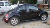
*Here's your Beetle
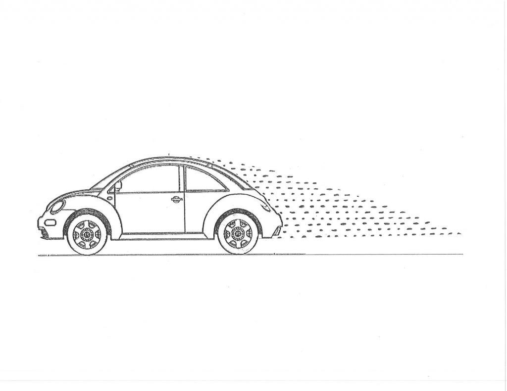
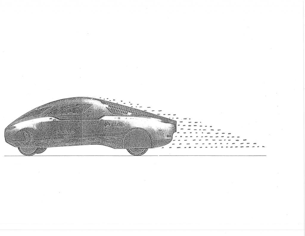
Here's the SolarWorld GT,it's roof is not ideal (It's a solar array)
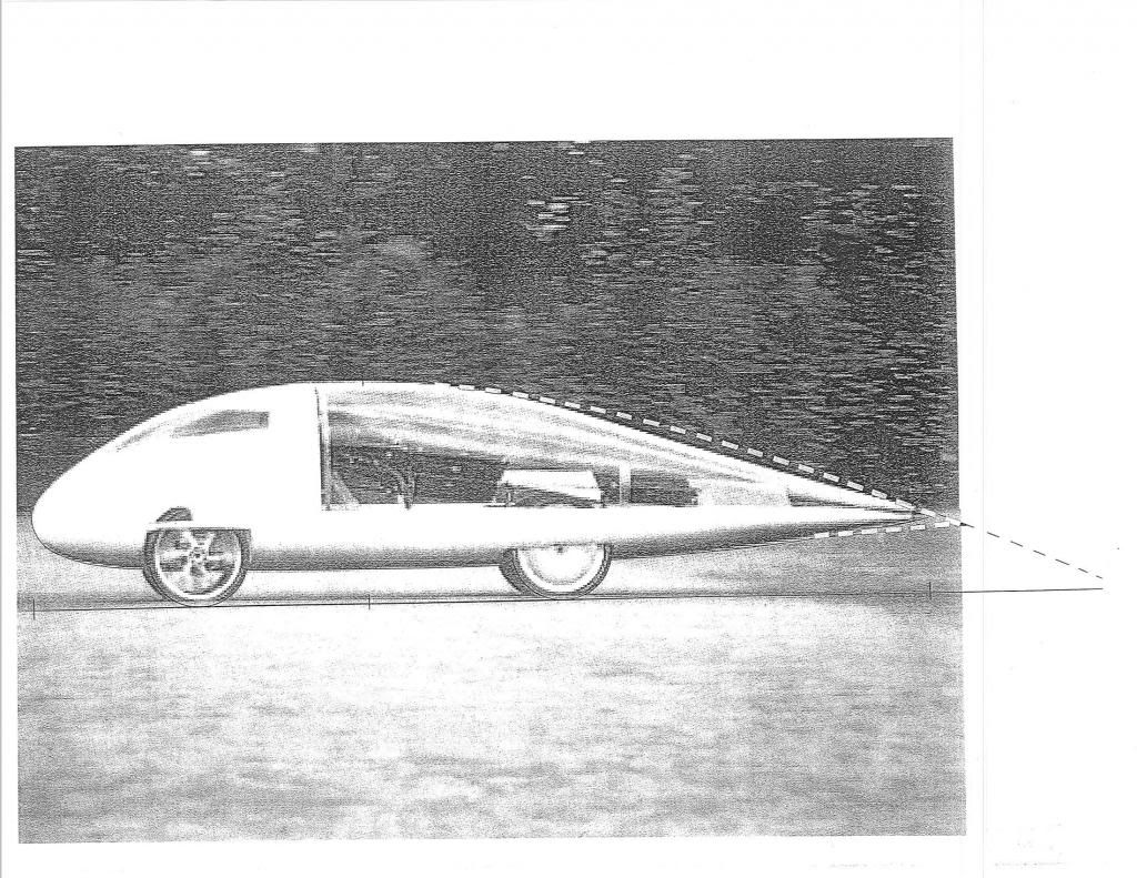
Here's Cambridge University's CUER,with Cd 0.10 vs 0.137 for Solar GT
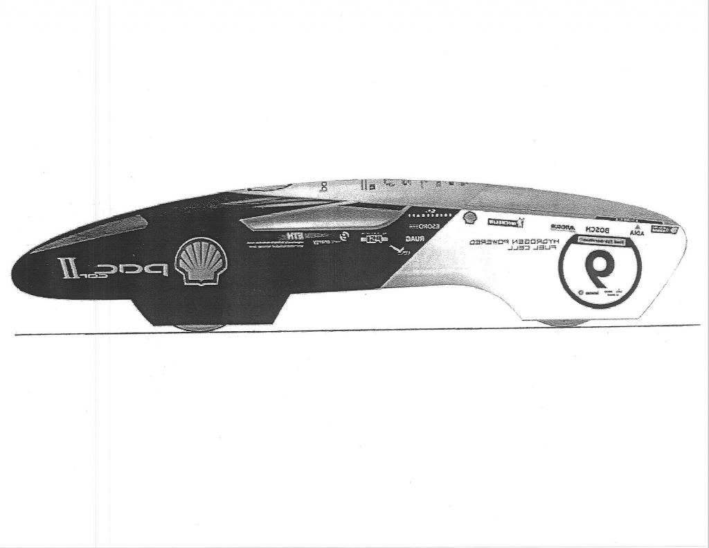
Here is PAC CAR II,Cd 0.075.
-------------------------------------------------------------------------
It is scientifically impossible to get low drag with steeper angles without artificial boundary layer control devices.
------------------------------------------------------------------------
The 'Aerodynamic Streamlining Template' is a scientific contour which was proved in the wind tunnel.There is nothing arbitrary about it.And there is no scientific evidence in the public domain in the last 92-years which suggests that we can beat it in any appreciable way.And that includes 'laminar' forms.
__________________
Photobucket album: http://s1271.photobucket.com/albums/jj622/aerohead2/
|
|
|
|
|
The Following User Says Thank You to aerohead For This Useful Post:
|
|
|
07-02-2014, 08:58 PM
|
#99 (permalink)
|
|
Drive less save more
Join Date: Jul 2011
Location: Vancouver Island, Canada
Posts: 1,189
Thanks: 134
Thanked 162 Times in 135 Posts
|
Thanks for the detailed response aerohead , I am back on track again .. I needed that brief as I was starting to try to out think the template , which you helpfully pointed out , can't be done.
The 1/32 model
I will post up a few photo's of the scale model Beetle in a few hours when I get back home.
__________________
Save gas
Ride a Mtn bike for errands exercise entertainment and outright fun
__________________
|
|
|
|
|
07-03-2014, 08:41 AM
|
#100 (permalink)
|
|
Master EcoModder
Join Date: Jul 2011
Location: Ann Arbor, Michigan
Posts: 4,158
Thanks: 120
Thanked 2,790 Times in 1,959 Posts
|
Quote:
Originally Posted by ecomodded
.......I needed that brief as I was starting to try to out think the template , which you helpfully pointed out , can't be done.
|
What cannot be done is to follow the template in plan view ( unless you have a 3-wheeled car) in true full 3D. This is why the following quote is so important.
Quote:
Originally Posted by aerohead
You may have the appearance of attached flow on the centerline,but you'll have attached longitudinal vortices produced which have high drag.
|
You may not be able to out think the template, but you cannot follow it either, unless you have a three wheeled or tapered plan car, or a blimp from which this shape was derived.
The template shape is for a "whole body" form, whereas most modifications we do to our existing cars can only be partial adaptations.
|
|
|
|
|
The Following User Says Thank You to kach22i For This Useful Post:
|
|
|