02-14-2011, 05:50 PM
|
#111 (permalink)
|
|
Master EcoModder
Join Date: Jan 2008
Location: Sanger,Texas,U.S.A.
Posts: 16,473
Thanks: 24,500
Thanked 7,436 Times in 4,817 Posts
|
wheelbase
Quote:
Originally Posted by RobertSmalls

cfg,
You are correct.
3. Slide the template forward or backward as desired. Cut away everything above the template with a sawzall, and fill everything below the template.
KB, Poka-Yoke was exactly what I had in mind in #83. 
But for the lower half of the template:
1. Align the ground planes in the images of both the template and the car.
2. Scale the template until its wheelbase matches the car's. No part of the car may extend below the template when loaded to its max weight.
Yep, I write op sheets on the weekends too. ") |
wheelbase is not a criteria for the template.What I did to the underside of the template 'vehicle' is only an illustration of the 'boundaries' we are asked to respect by the S.A.E. if we hope for our work to survive.If nothing falls below the 16 & 10-degree angle projections your good to go.
|
|
|

|
 Today Today
|
|
|
|
 Other popular topics in this forum...
|
|
|
|
|
02-14-2011, 06:02 PM
|
#112 (permalink)
|
|
Master EcoModder
Join Date: Jan 2008
Location: Sanger,Texas,U.S.A.
Posts: 16,473
Thanks: 24,500
Thanked 7,436 Times in 4,817 Posts
|
template comparisons
Quote:
Originally Posted by KamperBob
|
KB,looks like the wheels of the modified pickup are out of bounds with the template,kinda hanging below the ground-plane.
--------------------------------------------------------------------------
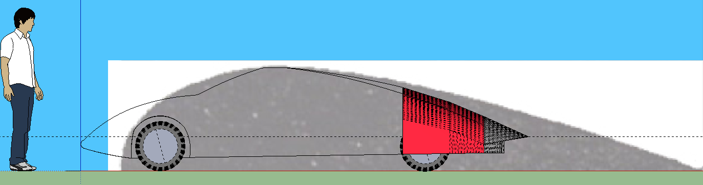
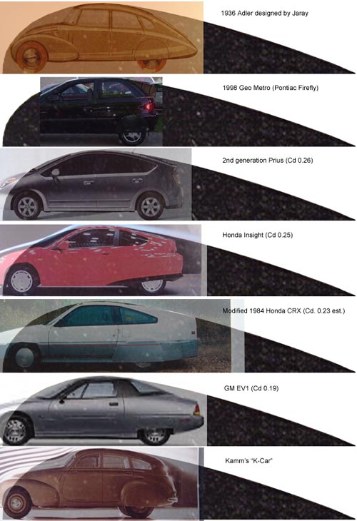
With respect to the Impact/EV-1/EV-2,the back is 'dirty' on those cars.They do not have attached flow over the backlite and boot.GM,at the time did not allow the 'Template' curvature do to strict outward vision requirements.They used it later on their hybrid van and today Cadillac uses it.
--------------------------------------------------------------------------
Dave Cloud's Dolphin is,I suspect', also a little 'dirty' in the back.That steep of curvature just won't maintain attachment,although he probably has fairly good vision out the backlite.
|
|
|
|
|
02-14-2011, 06:06 PM
|
#113 (permalink)
|
|
Master EcoModder
Join Date: Jan 2008
Location: Sanger,Texas,U.S.A.
Posts: 16,473
Thanks: 24,500
Thanked 7,436 Times in 4,817 Posts
|
instructions
Quote:
Originally Posted by RobertSmalls
Bob,
People will still take the teardrop and try to align it with the back of their truck's cab and the top of the tailgate. Instructions, in words, are needed.
Besides, the latest drawing steers you in the right direction, with a buildable design that's worth emulating.

While I had photoshop open, I took some measurements. Assuming 24" tires, the car in the template is 56" tall, or 1.05 Insights. The distance from the front bumper to the 80% mark is 18', or 1.11 Accords. I like it. |
There are two lengthy threads leading up to part-C which fully explain the template,its theory and use.If you haven't read them yet,check 'em out.
|
|
|
|
|
02-14-2011, 06:22 PM
|
#114 (permalink)
|
|
Master EcoModder
Join Date: Jan 2008
Location: Sanger,Texas,U.S.A.
Posts: 16,473
Thanks: 24,500
Thanked 7,436 Times in 4,817 Posts
|
shrink
Quote:
Originally Posted by cfg83
Frank -
I did an overlay :
 NOTE:
NOTE: My image may be incorrect if my choice for "apex/center of camber" is incorrect.
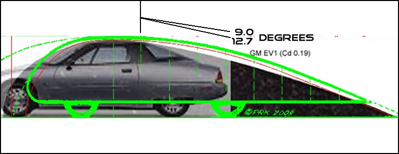
The (very) thin red line is the latest overlay we are looking at. The thicker green line is another overlay base on this image :
The 9.0 degrees is an interpretation of the red and green lines. The 12.7 degrees is the slope of the "shadow" over the EV-1. The EV-1 "shadow" is closer to a straight line from the apex, while the other slopes are more more curved (I hope that makes sense).
Base on the slopes I am seeing, I am going to split the difference and say that the "goal" should be an angle of close to 11 degrees (at least for the EV-1).
CarloSW2 |
I think the green original form needs to be shrunk down a smidgeon.We're working with the outer extremities of the image.
--------------------------------------------------------------------------
As far as the angles go,the intention is to locate the point of interest along the template,then ascertain the actual tangent angle at that point,splitting the point with a straightedge,then using protractor to find the angle.
The drawing I used is 30-inches in length.The closer you get to full scale,the higher the accuracy.
Some angles are given at each 10 % aft-body increment.
-------------------------------------------------------------------------- And remember,the EV-1 is 'dirty' in back.It suffers flow separation at 22-degrees.
|
|
|
|
|
02-14-2011, 06:27 PM
|
#115 (permalink)
|
|
Master EcoModder
Join Date: Jan 2008
Location: Sanger,Texas,U.S.A.
Posts: 16,473
Thanks: 24,500
Thanked 7,436 Times in 4,817 Posts
|
3.5-degrees @ 20%
Quote:
Originally Posted by cfg83
RobertSmalls -
Ok, here's the revised version, and I agree that they are very similar :
Even though I have been using the thick overlay incorrectly in previous posts, I think the inside/outside of the thick line is "close" enough and I feel I needed to see the vehicle for easier mod-visualization.
With that said, I will probably switch to this one :
It is now a 16-color gif with only black and white being used. This makes it easy to do transparent overlays. The above image is at 780 pixels for fitting into an ecomodder album, but I will attach a non-downsized image in a subsequent post.
CarloSW2 |
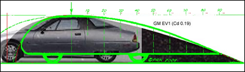
On the template,the 20% aft-body position should be 3.5-degrees.
|
|
|
|
|
02-14-2011, 06:40 PM
|
#116 (permalink)
|
|
Master EcoModder
Join Date: Jan 2008
Location: Sanger,Texas,U.S.A.
Posts: 16,473
Thanks: 24,500
Thanked 7,436 Times in 4,817 Posts
|
2.5
Quote:
Originally Posted by Frank Lee
I found airfoils here: Airfoil Investigation Database - Showing NACA 0021
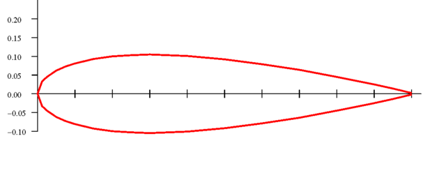
Then fattened the NACA 0021 profile 2x (that ground plane thing):
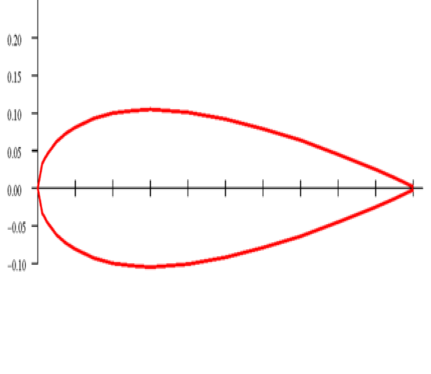
The NACA 0018 is listed as having somewhat lower drag vs the 0021; it appears they are the same shape only reproportioned e.g. 0018 is 18% as thick as it is long while the 0021 is 21% w/l. Here is the 0018 fattened 2x:
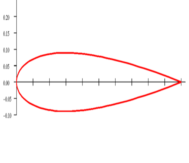
And they look like this template:
NOW, bear in mind that these airfoil profiles are 2-D. I came across this (slightly edited by me here):
The NACA 0018 reproportioned as above:
 |
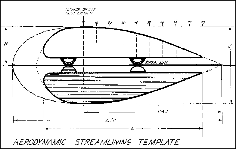
Frank,the template,as mentioned in the thread,is based on the 2.5:1 streamline body of revolution as depicted by Hucho,at Cd 0.04 and Cd 0.08 in ground-reflection,after Prandtl.
With wheels it goes to Cd 0.13.With wheel fairings it goes to as low as Cd 0.089,as per GM's results with Sunraycer.
My drawing is a *******ization of Hucho's image and W.A.Mair's 22-degree boat-tail for the sake of construction simplicity.It's not mathematical but I quarantee it.
|
|
|
|
|
02-14-2011, 06:47 PM
|
#117 (permalink)
|
|
Master EcoModder
Join Date: Jan 2008
Location: Sanger,Texas,U.S.A.
Posts: 16,473
Thanks: 24,500
Thanked 7,436 Times in 4,817 Posts
|
exactly
Quote:
Originally Posted by RobertSmalls
Phil,
Consider a bread truck. Any point along the roof of its box is equally valid as the point of maximum camber. A similar sad story goes for most full sized pickups.
If you were to slice the template vertically at the 0% mark and insert a rectangle (of any width), the drag coefficient would go up due to skin friction, but you could still use the template to guarantee attached flow, right? So a bread truck or a minivan with a boat tail grafted on the back would do okay, though not as well as the same treatment applied to a Prius.
|
That's it! At the back,that's your zero-point,and you're just doing a boat-tail as Mair did,or NASA,or my VW bus. |
|
|
|
|
02-14-2011, 08:38 PM
|
#118 (permalink)
|
|
Pokémoderator
Join Date: Dec 2007
Location: Southern California
Posts: 5,864
Thanks: 439
Thanked 532 Times in 358 Posts
|
aerohead -
Quote:
Originally Posted by aerohead
*The subject vehicle will have a point of maximum roof camber and that's a fixed point,it's not negotiable.
* The template has its zero-point or maximum roof camber and it's a fixed point and cannot be moved.
* If the two images are scaled such that the height of their max roof camber points are identical and then aligned together,this is the only condition in which the template can function.The template cannot function with any other alignment.
* If the roof of the subject vehicle conflicts with the template,it only indicates the aerodynamic compromise and we'll have to do the best with what we've got to work with.
|
Thanks. And rats.
Sometimes physics can be so mean,  .
CarloSW2 |
|
|
|
|
02-14-2011, 08:46 PM
|
#119 (permalink)
|
|
Pokémoderator
Join Date: Dec 2007
Location: Southern California
Posts: 5,864
Thanks: 439
Thanked 532 Times in 358 Posts
|
aerohead -
Quote:
Originally Posted by aerohead
On the template,the 20% aft-body position should be 3.5-degrees.
|
Ok, here's the corrected image :

CarloSW2
. |
|
|
|
|
The Following User Says Thank You to cfg83 For This Useful Post:
|
|
|
02-23-2011, 07:09 AM
|
#120 (permalink)
|
|
2000 Honda Insight
Join Date: Jul 2010
Location: Minneapolis, MN
Posts: 57
Thanks: 5
Thanked 13 Times in 11 Posts
|
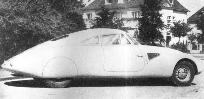
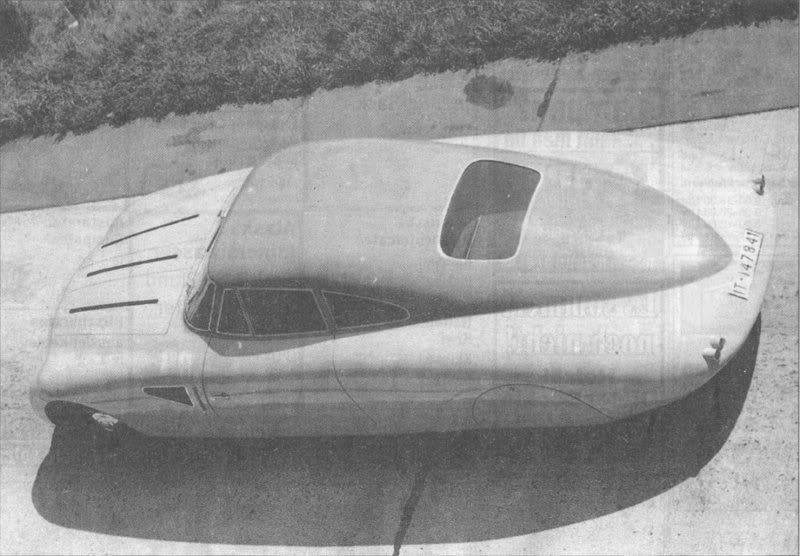
I have no side image of this, but here is some eye candy and the only information I have. I have no way to verify this information so take it at whatever value you perceive. This seems to fit the ideal shape quite well above. A bit steep on the back perhaps but the front seems to have the idea.
1937 Schlor Pillbug 0.13 cD

1939 Maybach Stromlinienkarosserie 0.16 cD with flat glass. 0.14 cD with curved glass.
|
|
|
|
|