 01-04-2012, 07:31 PM
|
#11 (permalink)
|
|
home of the odd vehicles
Join Date: Jun 2008
Location: Somewhere in WI
Posts: 3,892
Thanks: 508
Thanked 868 Times in 654 Posts
|
Quote:
Originally Posted by Formula413

A grid charger is very expensive, and I'm somewhat reluctant to commit to that if I will still need to tear down the pack and find the bad subpacks.
|
??? Get a small motor run cap and a bridge that gives you about a 1/8-1/2 amp output at 60hz 220v. It might cost as much as $20.
Anyway You can't overcharge NiMH so long as the charge is VERY slow. So a timer and a cap charger is all you need to start equalizing the whole kit and kabootle.
Do it daily for about 4-12 hours (depending on rate and desired overcharge) and maybe it will start coming back or if nothing else will be usuable after each "recharge"
|
|
|

|
 Today Today
|
|
|
|
 Other popular topics in this forum...
|
|
|
|
 01-05-2012, 06:16 PM
|
#12 (permalink)
|
|
EcoModding Apprentice
Join Date: Jan 2008
Location: usa
Posts: 105
Thanks: 18
Thanked 30 Times in 19 Posts
|
Quote:
Originally Posted by MetroMPG

You may be right, but Mr Smalls suggested you can build your own for a very reasonable price:
Though it sounds like he may have hunted/waited for inexpensive components. I haven't looked into it yet.
|
I built mine for ~ $60 The 48 volt meanwells were on sale on Ebay for 4 for $25 (I think).
http://99mpg.com/Data/resources/down...balancer_2.pdf
http://99mpg.com/Projectcars/mimapackwhack/
Last edited by silverinsight2; 01-05-2012 at 06:22 PM..
|
|
|

|
 01-06-2012, 11:06 AM
|
#13 (permalink)
|
|
Batman Junior
Join Date: Nov 2007
Location: 1000 Islands, Ontario, Canada
Posts: 22,541
Thanks: 4,085
Thanked 6,989 Times in 3,619 Posts
|
battery pack-ectomy
|
|
|

|
 01-06-2012, 11:22 AM
|
#14 (permalink)
|
|
Batman Junior
Join Date: Nov 2007
Location: 1000 Islands, Ontario, Canada
Posts: 22,541
Thanks: 4,085
Thanked 6,989 Times in 3,619 Posts
|
Pack removal took about an hour and a half, taking my sweet time, working carefully, methodically. I took more than a few precautionary voltage readings & made notes along the way.
If you've done the job before, or watched someone do it, obviously it will take much less time. Half an hour is a reasonable guess if you boogie.
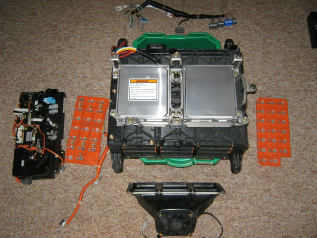
The assembly weighs about 80 lbs / 36 kg. Removal from the car is pretty awkward for one person, but doable if you're careful and plan the intermediate moves (and have a good back). One risk is damaging exposed components on the junction side (left in the photo) if you screw up and bang it around. (Junction side components = wires/cables, connectors, bus bars, contactors, resistor, fuse, induction ammeter coils, etc.)
I'm able to work on many things at my shack with wood heat & small photovoltaic setup. But at this time of year I don't think I'll have enough reserve power from the solar system for the charge/discharge cycles to come (it's fine for lights, tunes & occasional small power tool use - that's about it).
So I brought the pack to the house. Also, the house will be at a more consistent temperature, which is also important for getting quality testing data from the subpacks/sticks. |
|
|

|
 01-06-2012, 11:29 AM
|
#15 (permalink)
|
|
Administrator
Join Date: Dec 2007
Location: Germantown, WI
Posts: 11,203
Thanks: 2,501
Thanked 2,589 Times in 1,555 Posts
|
Woo, nice job. You should get a perspective shot so people actually know how small that pack really is (its not big).
|
|
|

|
 01-06-2012, 12:02 PM
|
#16 (permalink)
|
|
Master EcoModder
Join Date: Jun 2008
Location: Earth
Posts: 5,209
Thanks: 225
Thanked 812 Times in 595 Posts
|
Quote:
Originally Posted by Daox

You should get a perspective shot so people actually know how small that pack really is (its not big).
|
Roughly the size of a standard PC tower case, especially if you take the fan housing off before pulling it out of the car. |
|
|

|
 01-06-2012, 12:05 PM
|
#17 (permalink)
|
|
Batman Junior
Join Date: Nov 2007
Location: 1000 Islands, Ontario, Canada
Posts: 22,541
Thanks: 4,085
Thanked 6,989 Times in 3,619 Posts
|
Yup. Or I can just tell you!
Quick measurement =
~cm: 51 x 61 x 22
~inches: 20 x 24 x 9
That's the full extents: including the standoffs on top, and the mounting brackets sticking out from each corner, and the fan housing.
|
|
|

|
 01-06-2012, 01:54 PM
|
#18 (permalink)
|
|
Master EcoModder
Join Date: Sep 2009
Posts: 5,927
Thanks: 877
Thanked 2,024 Times in 1,304 Posts
|
I was thinking about buying another Insight, but after reading about the battery issues and having my own battery replaced under warranty, I'm not sure if it is a good long term proposition.
One thing you might consider.
Since the Honda's are known to have problems, apparently due to a combination of the series configuration and heat dissipation, maybe it would be a good idea to consider your whole pack as one very long battery.
Record the strength of each 6 cell stick and graph it as a straight line.
Then look at the line and consider rearranging the sticks in the pack to put the weakest cells where the strongest were, then the strongest where the weakest were.
Kind of like rotating tires to even out wear patterns, but this might actually make any repair last considerably longer since the weakest stick is going to be your future problem.
A tactical graph of all of the individual sticks should show you where the sticks tend to suffer the most and where they suffer the least. Reversing the arrangement should help them to stay fairly balanced much longer than putting the weakest stick where it was before and subjecting it to the same conditions as before.
Might even become a maintenance procedure, where every XXXX numbers of miles you rotate the sticks to the best and worst locations in the pack assembly.
Weakest stick best location, strongest stick worst location.
Might be worth a try.
regards
Mech
|
|
|

|
 01-06-2012, 02:14 PM
|
#19 (permalink)
|
|
Batman Junior
Join Date: Nov 2007
Location: 1000 Islands, Ontario, Canada
Posts: 22,541
Thanks: 4,085
Thanked 6,989 Times in 3,619 Posts
|
Neat! I was actually wondering about that.
Each time I've received a used replacement pack of flooded golf cart batteries for the electric Metro, I made a note of where each battery was located in the previous donor vehicle's pack.
Often the ones that turned out to be weaker were the "meat" in the previous pack sandwich, which would have gotten hotter compared to the ones that were the buns, if you get my drift. (Suddenly I'm hungry for lunch...)
I'd be surprised if someone on insightcentral hasn't already compared stick location inside the pack vs. health.
But I'll definitely keep notes as I move along.
|
|
|

|
 01-06-2012, 02:52 PM
|
#20 (permalink)
|
|
Batman Junior
Join Date: Nov 2007
Location: 1000 Islands, Ontario, Canada
Posts: 22,541
Thanks: 4,085
Thanked 6,989 Times in 3,619 Posts
|
 Center
: battery pack/module case. The two magic silver electronic boxes on top are: BCM (Battery Condition Module - left side) and MCM (Motor Control Module -right)
Top (above pack case): wiring harness
Right: bus plate/cover - contains bus bars which interconnect the 20 NiMH sticks/subpacks, through-connected with bolts.
Bottom: battery module cooling fan/duct
Left: junction side components (including wires/cables, connectors, bus bars, contactors, resistor, fuse, induction ammeter coils, etc.); orange plate/bus cover bolted to ends of sticks & battery case

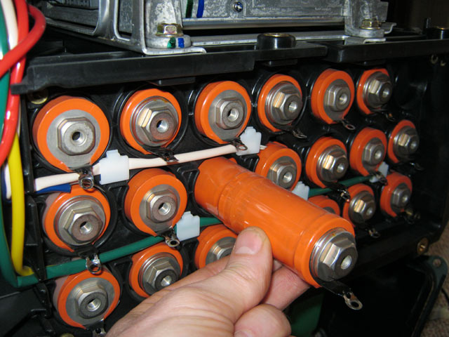
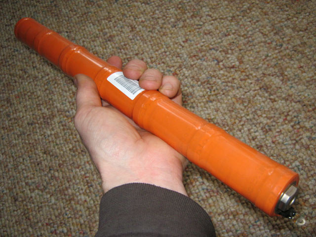
20 sticks/subpacks containing 6 "D" size NiMH cells each. Arrayed so the bolt connections through the end plates create a series string of 120 cells in the pack.
The nominal voltage per cell is 1.2 volts, for a total pack voltage of 144 volts (1.2 V x 120 cells).
The small ring terminals on each stick are the ends of a strip of 6 (one for each cell) PTC (positive temperature coefficient - "posistor") devices - through this strip, the car's electronics can monitor temperature changes in the pack. (There are additional temperature sensors in the pack.)

I'm free!
|
|
|

|
|